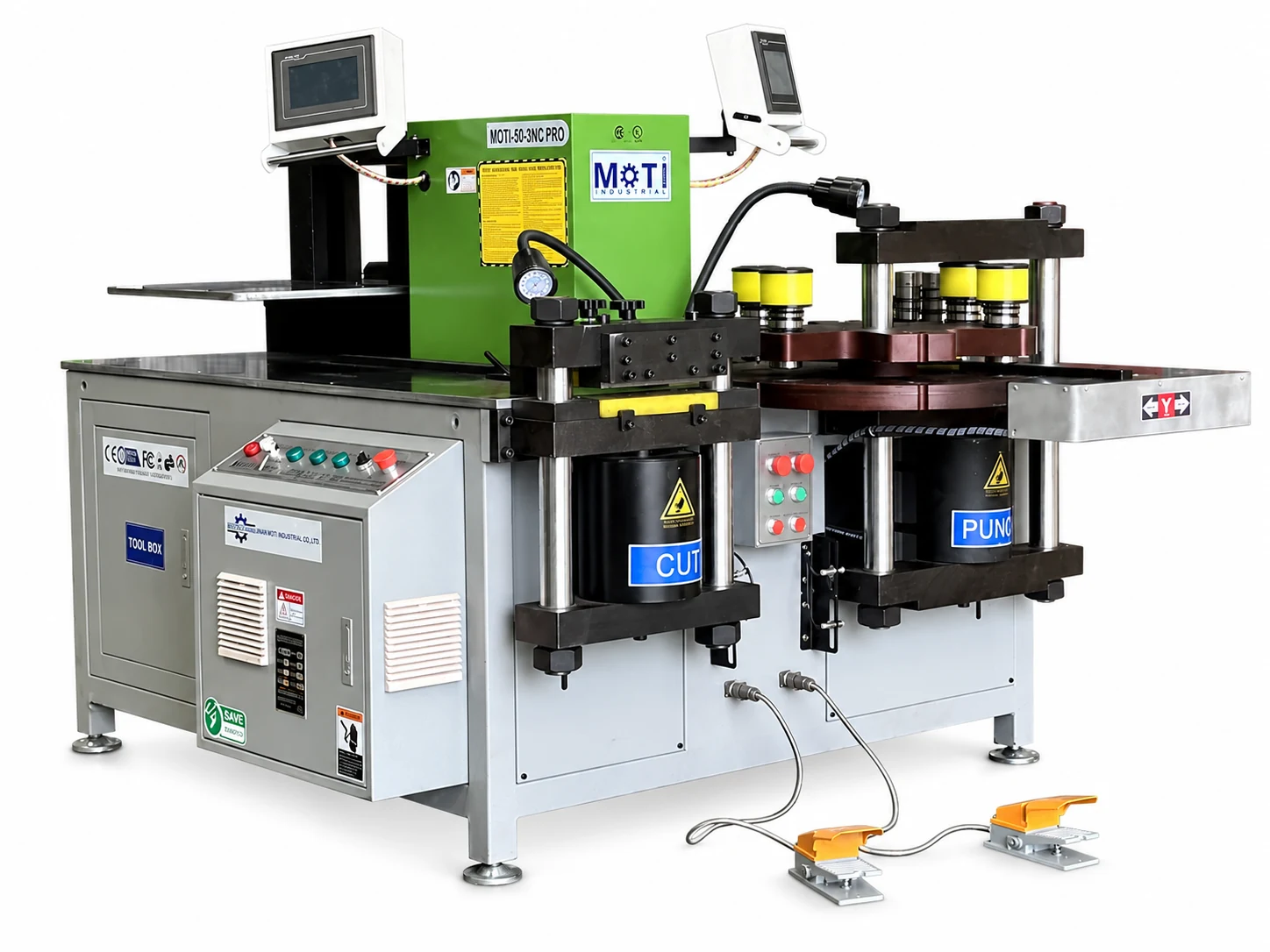
Servo 3-in-1
MOTI-50-3NC PRO Servo Busbar Processing Machine
Four servo positioning axes for repeated work.
The 50-3NC PRO processes a 16 × 250 mm main working range and uses four servo positioning axes across cutting, punching and bending. Servo positioning helps with repeated settings; operators still handle workpieces between operations.
Thickness × width
16 × 250 mm
Send your drawing to check material, tooling and operation limits.
THE RIGHT APPLICATION
Servo positioning for jobs that repeat dimensions across three operations.
The MOTI-50-3NC PRO combines cutting, punching and bending within a published 16 × 250 mm range. Its four servo positioning axes address a different purchasing question from capacity: how often an operator must reset a length or hole coordinate. Consider the PRO for repeated hole patterns and frequently recalled dimensions. Operators still load, transfer and support the workpieces; evaluate the assistance using one of your normal production drawings.
01 TECHNICAL OVERVIEW
Know the working range.
Compare these working limits with your part. Your quotation identifies the supplied machine version and tooling.
| Cutting capacity (thickness × width) | 16 × 250 mm |
|---|---|
| Punching capacity (thickness × width) | 16 × 250 mm |
| Main bending capacity (thickness × width) | 16 × 250 mm |
| Force per process | 500 kN |
| Net weight | 1750 kg |
| Gross weight | 1800 kg |
| Electrical supply | 3-phase, 380 V, 50 Hz |
| Punching diameter | 4.3–34 mm |
| Main motors | 3 × 5.5 kW |
| Cutting X-axis positioning | 1,000 mm |
| Punching X / Y positioning | 500 / 1,000 mm |
| Bending gauge positioning | 500 mm |
Before you choose
The headline capacity is an initial selection reference. Hole size, edge distance, bend direction and tooling can impose separate limits. Request a drawing review for your application.
See which position is controlled
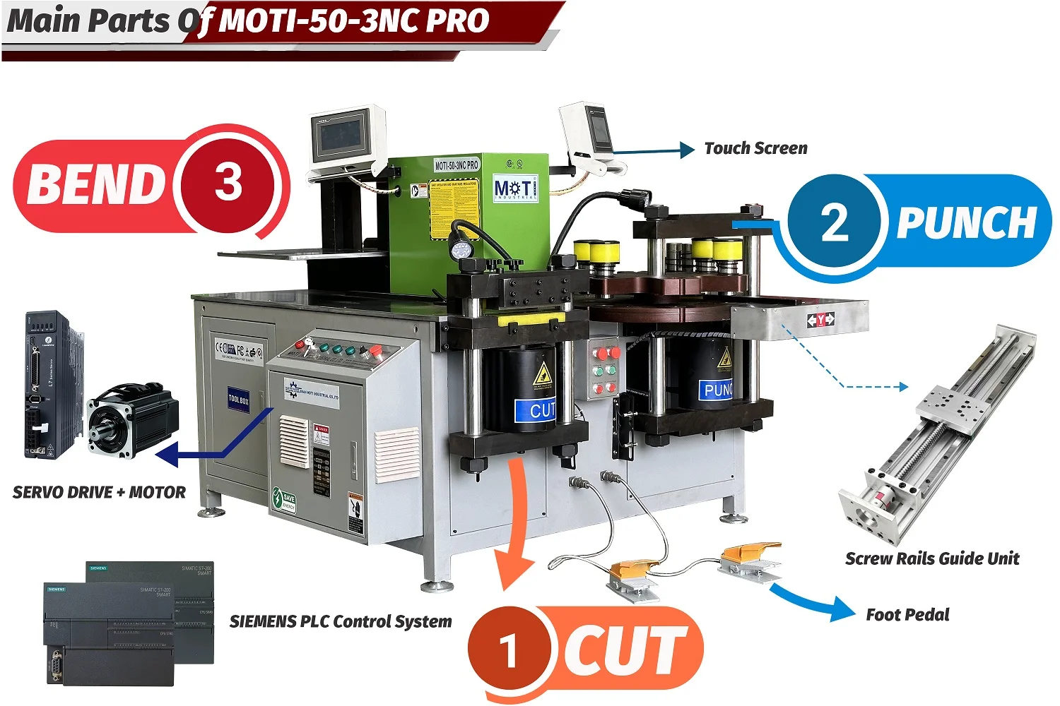
Four servo axes cover the cutting stop, punching X/Y coordinates and bending gauge. The control sets a target position for the relevant operation. Bring a repeated part drawing to compare setup and positioning with your current process.
02 INSIDE THE PROCESS
See how the work gets done.
Equipment details, positioning and the workpiece requirements to discuss for this model.
01
Cutting: a 1,000 mm X axis
The cutting station provides a servo positioning axis with a published 1,000 mm travel. It helps set the cutting reference for successive lengths. This is axis travel, not an unlimited stock-length rating. Include the support and handling arrangement for your longest bar when reviewing the layout.
02
Punching: position in two directions
The published punching travels are 500 mm on X and 1,000 mm on Y. These axes help locate the workpiece relative to the punch for repeated patterns. The punch-diameter range is 4.3–34 mm; the tool, material and thickness still need to be checked together.
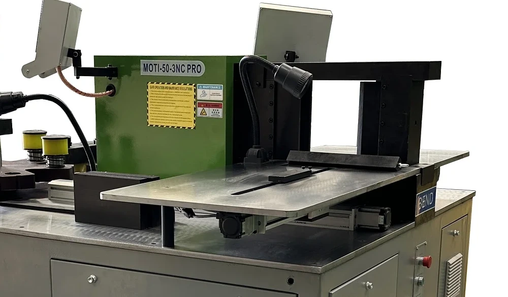
03
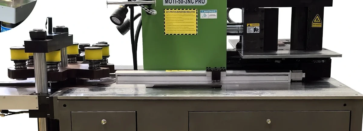
Bending: a 500 mm positioning gauge
A servo bending gauge provides 500 mm positioning travel, with a Siemens controller listed for the machine. Review gauge contact, the chosen bending tool and how a previously formed flange clears the machine. Positioning travel is distinct from bend capacity and finished-part accuracy.
03 TOOLS & FINISHED PARTS
Tooling, configuration and options
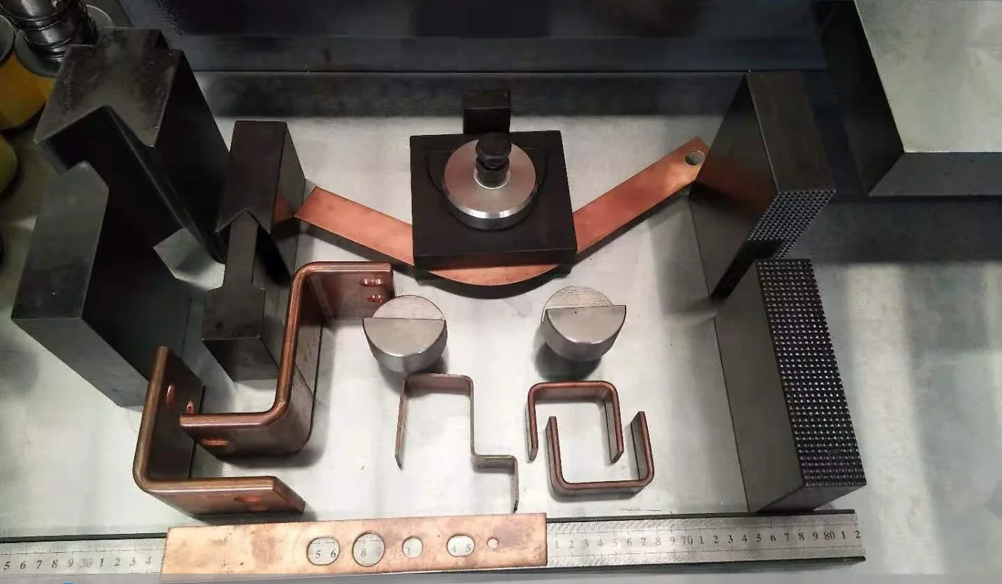
Standard tooling: Eight punching die sets, main-direction, U and alternate-direction bending tools, embossing tools, and fitted upper and lower cutting blades are listed for the PRO. Specify the required punch sizes and each tool orientation.
Options: Twisting and single-operation forming tools are designed from the finished-part drawing and quoted separately.
Eight punching die sets
Eight punching die sets are listed in the standard PRO package. Specify the round-hole diameters or slot dimensions needed for your parts.
Bending and embossing tools
Main-direction, U-shaped and alternate-direction bending tools, plus embossing tools, are listed as standard accessories for the PRO. Confirm the drawing and orientation for each tool.
Upper and lower cutting blades
Upper and lower blades are fitted standard accessories for the PRO cutting station.
Optional custom tools
Twisting tools and single-operation forming tools are available for discussion from the finished-part drawing.
04 FROM SELECTION TO PRODUCTION
Review a complete working cycle.
Choose a repeat job
Bring a drawing with several cut lengths or hole coordinates. List the quantity, material and tooling used today. Keep these assumptions identical when comparing the standard machine and the PRO.
Demonstrate the complete cycle
Include setting the gauges, loading, positioning, operating each station, transferring the part and checking the result. Servo motion time alone does not describe finished parts per hour.
Specify the delivered system
The published machine is three-phase 380 V, 50 Hz with three 5.5 kW motors. State your actual supply, control language and preferred tool list. Include software, manuals, training and any electrical variation in the agreed scope.
05 MOTI-50-3NC PRO · QUESTIONS
Before you choose.
Both models are in the 16 mm thickness class. The PRO specifies a 16 × 250 mm main working range; standard 50-3NC width is defined by configuration. The PRO adds four servo positioning axes, so compare the positioning work your parts require as well as the selected machine’s operation limits.
It provides servo positioning at the three workstations. Loading, unloading and transfers still require operator handling. A dedicated automatic punching and shearing line is a separate configuration.
No fixed hole list is stated for every order. The product information allows the die sizes to be customized. Send the complete list of round holes and slots so the quotation can identify each tool.
The machine has a net weight of 1,750 kg and a gross weight of 1,800 kg. The final quotation and packing list specify labelled packing dimensions and the requirements for transport and unloading.
06 COMPARE OPTIONS
Find the right level of capability.
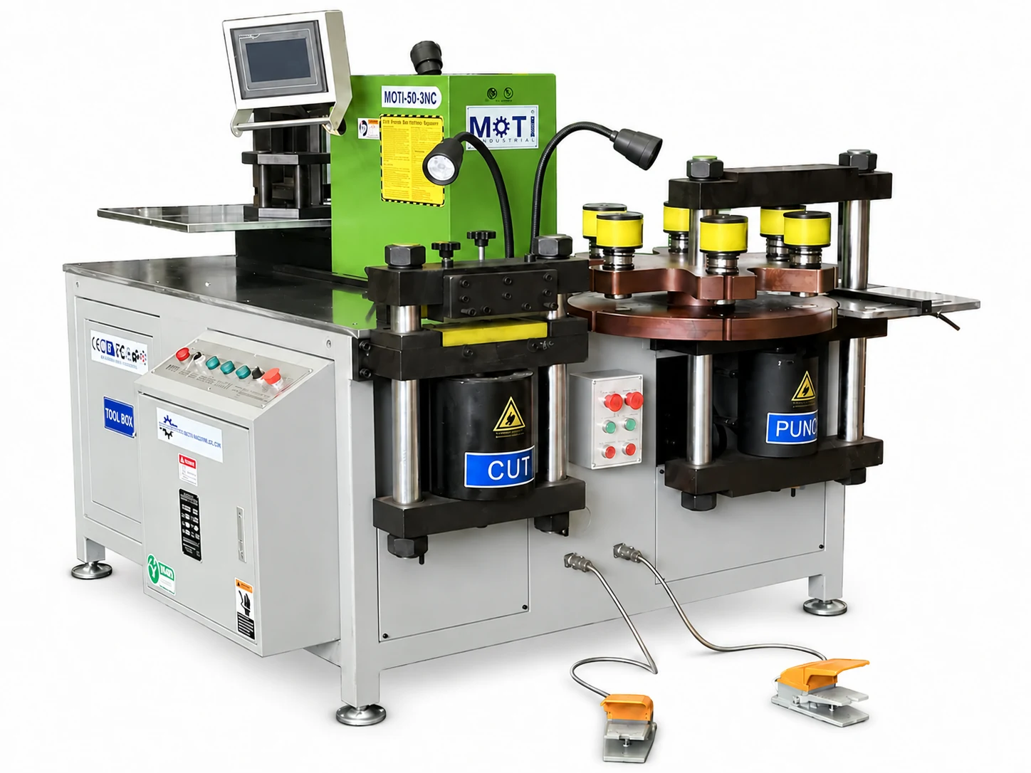
3-in-1 workstation
A wider working range for panel production.
16 mm thickness class
Thickness × width · operation limits apply
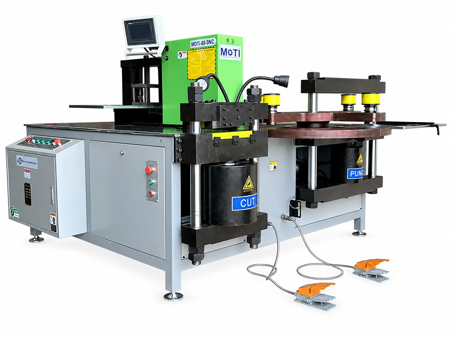
Heavy-duty 3-in-1
For thicker and wider copper busbars.
20 × 300 mm
Thickness × width · operation limits apply
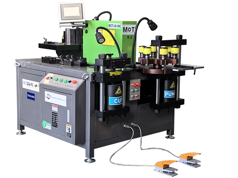
3-in-1 workstation
Everyday busbar fabrication for panel workshops.
12 × 160 mm
Thickness × width · operation limits apply
Evaluate Servo Positioning with Your Parts
Review the standard-versus-PRO differences, then test the positioning steps that matter in your production.
Tell us about the busbars you make.
Share your material, maximum thickness and width, and the cutting, punching or bending work you need. A drawing or a sample requirement helps us discuss the right machine and tooling.
We use your details to respond to your machine enquiry. For drawings, use the email or WhatsApp links below.
Have a drawing? Attach your PDF, CAD file or clear part photo in email or WhatsApp. Include material, thickness, width and quantity.