
By MOTI Industrial · 16 September 2026
Servo positioning is useful only when it reduces the manual locating work in your actual production route. A list of axes cannot show whether the machine will handle your hole patterns, bend locations and batch changes efficiently. The practical test is to run representative parts and record what the operator still has to locate, rotate, move and inspect.
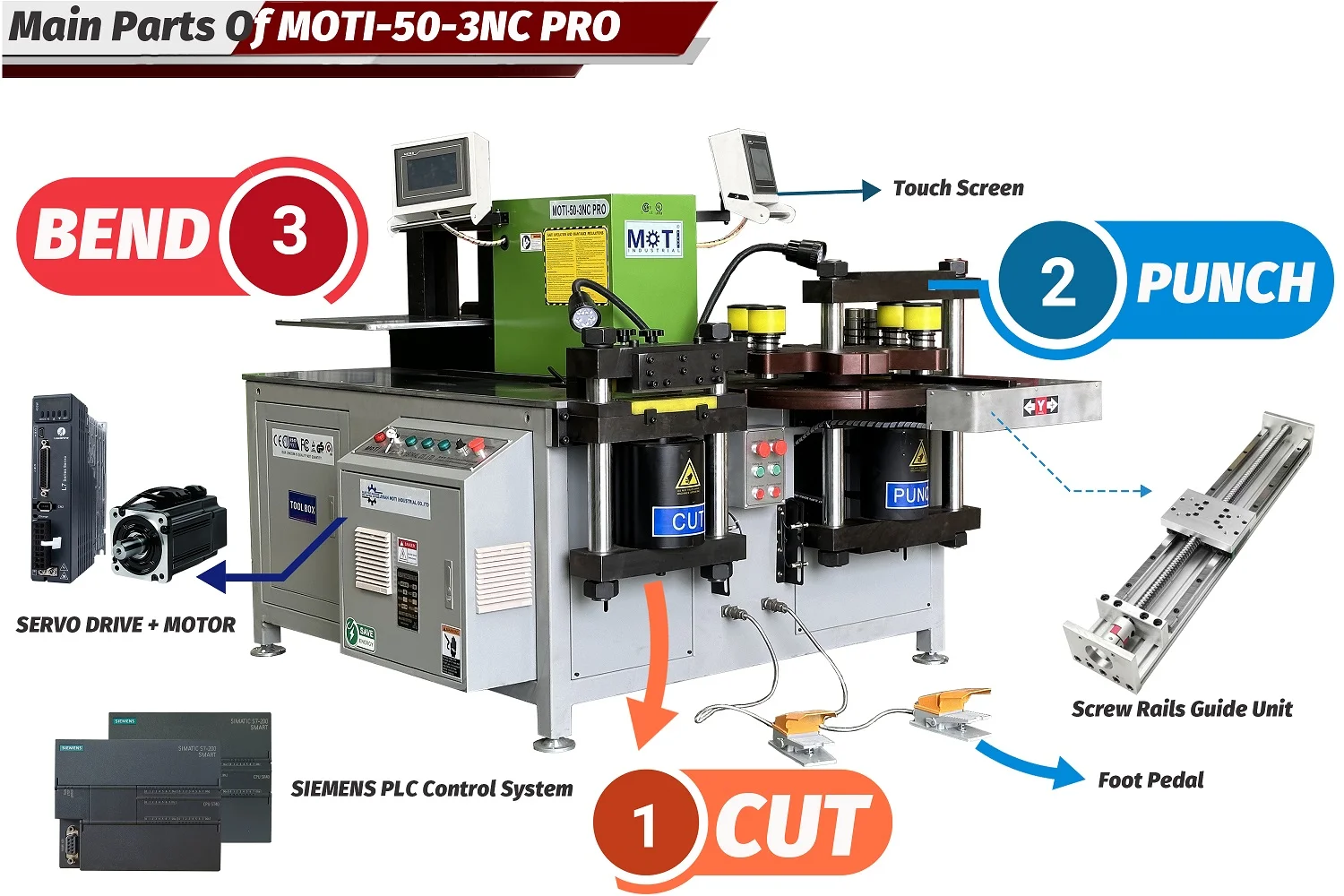
For the MOTI-50-3NC PRO, the published positioning layout identifies four axes: cutting X, punching X and Y, and a bending backgauge. Use these labels as the start of a trial plan. Do not turn them into a claim of automatic loading, unloading or transfer between workstations.
Start with the current positioning steps
Before the trial, document how the same parts are made today. Mark the drawing datum, each manual stop or line mark, every repositioning step, any part rotation, the move between cutting, punching and bending, and the inspection points. Record the first setup separately from repeat pieces. This gives the servo trial a real baseline instead of a vague comparison with “manual work.”
Choose at least three drawings that represent the production mix: a frequent part, a part with several hole positions, and a part that causes awkward locating or a regular changeover. Include material, thickness, width, finished orientation and drawing revision. The earlier busbar hole-pattern drawing checklist explains how to make the punching datum, slot direction and mirrored views unambiguous.
Map every drawing dimension to a machine axis
Create a simple table before running parts. For cutting, identify the length reference controlled by cutting X. For punching, identify which hole-centre dimensions depend on punching X and which depend on punching Y. For bending, identify the flange or bend-position reference that the backgauge locates. Dimensions outside those movements still need an operator method, fixture or separate process.
Confirm the coordinate direction, zero reference and physical workpiece edge used by each program. Match the program name to the current drawing revision. A correct value entered from the wrong end of the bar can create a consistent but unusable part. The trial record should therefore pair screen values with a marked drawing and the physical datum on the sample.
The standard versus servo busbar machine guide covers the wider selection decision. This trial should answer a narrower question: which locating steps disappear, which remain and how the change affects your own part family.
Test punching positions across the real part family
Use the normal hole pattern first, then a pattern near the smallest and largest positions that your drawings require. Include repeated hole spacing, a change in the Y position and any part that must be turned or re-referenced. Check the first piece and several consecutive pieces against the same drawing datum. Do not judge positioning from a single centre hole.
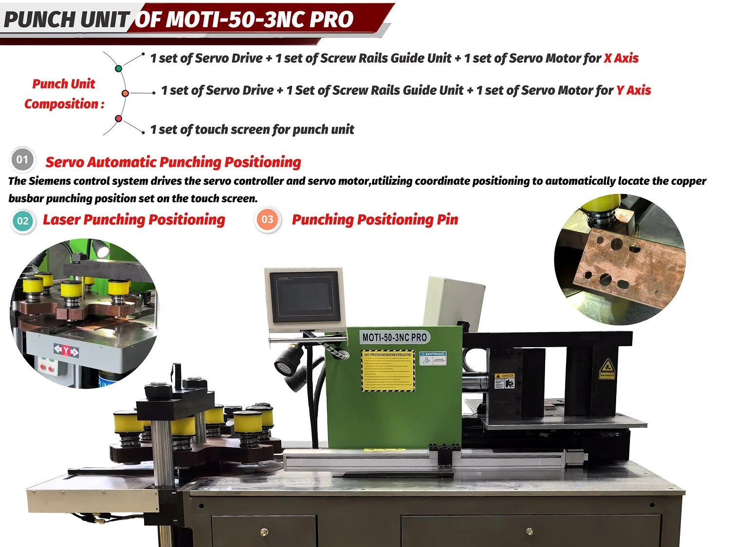
For each part, record program selection, zero setting, workpiece loading, any manual alignment, axis moves, punching sequence, rotation and final measurement. The goal is to expose the complete operator route. A machine can position two coordinates while the process still depends on manual orientation or transfer.
Run the bending trial from the finished-part datum
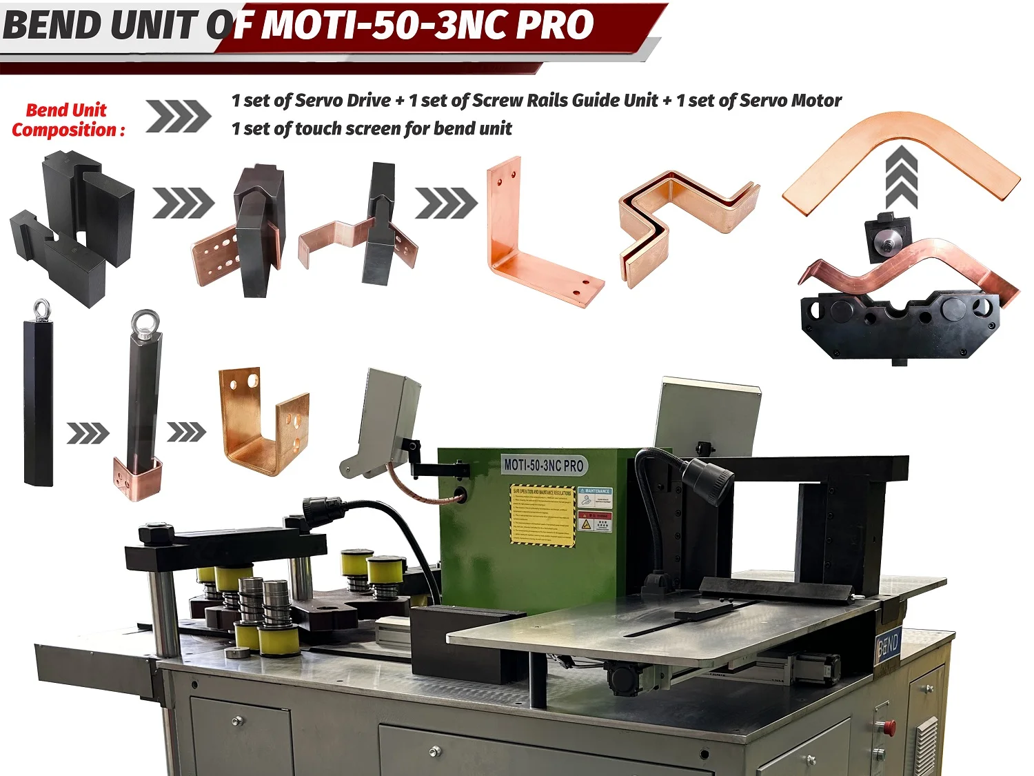
For bending, define whether the backgauge reference is taken from a cut end, hole centre, previous bend or another controlled feature. Check that the chosen reference remains accessible after earlier operations. Test a common flange, a shorter or more constrained flange from the real drawing set, and a part with more than one bend when that is part of production.
Measure the finished relationships that matter in assembly, such as hole-to-bend distance, flange length or overall offset. Keep bend-angle control and bend-position control as separate observations. A good position does not prove the requested angle, and a correct angle does not prove the mounting holes will align.
The machine still needs the correct tooling and a workpiece within its confirmed range. The published main busbar range for both the MOTI-50-3NC and MOTI-50-3NC PRO is 16 × 250 mm. That shared range allows a like-for-like screening discussion, but it does not establish that every drawing or tool is suitable without review.
Separate first setup, repeat production and changeover
Time and observe three stages independently. The first setup includes drawing check, tool installation, program creation or selection, zero setting and first-piece inspection. Repeat production starts only after the first piece is accepted. Changeover includes removing the previous setup, installing the next tool or program, setting the new datum and approving the next first piece.
Use an A-B-A sequence when changeover matters: run part A, change to part B, then return to part A. This shows whether the saved program and physical references reproduce the earlier setup. The batch changeover questions provide a detailed record format, while the production cycle-time trial explains why handling and inspection belong in the comparison.
Include interruptions and recovery
Ask the operator to stop after a completed operation, confirm the last finished step and resume under the supplier’s normal procedure. Check how the program, axis position and workpiece reference are verified before the next move. Also test a normal drawing revision or batch change so the team can see how programs are identified and protected from selecting the wrong part.
Do not create a fault or bypass a safety function for the trial. The useful question is whether the documented recovery process makes the next part traceable and inspectable after an ordinary interruption.
Use a written acceptance matrix
List each station, axis, sample drawing, datum, operator action, measured feature and result. Add columns for first setup, repeat pieces, A-B-A return and recovery. Record observations rather than expected marketing outcomes. If a manual step remains, decide whether it is acceptable, needs a fixture or changes the equipment choice.
Send MOTI three representative drawings, your current positioning steps and the expected batch mix. We can map the cut, punch and bending references to a part-based trial before you compare the standard MOTI-50-3NC with the servo-positioning PRO configuration.
Sources: MOTI-50-3NC PRO and MOTI-50-3NC published product information, checked 15 September 2026, plus MOTI’s internal equipment-selection and trial-review records. Axis names and the 16 × 250 mm main range are manufacturer-published values; production improvement must be measured on the buyer’s own parts.