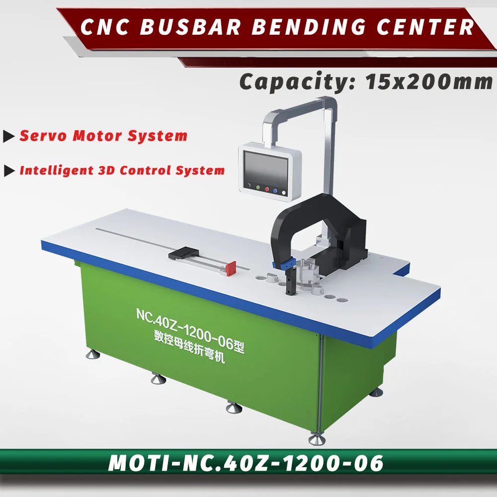
Servo CNC bending center
MOTI-NC.40Z-1200
Dedicated bending with a 160 mm width.
15 × 160 mmThickness × width · operation limits apply

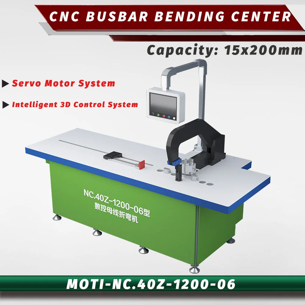
NC.40Z series illustration. The original image contains mixed model labels; final appearance and configuration may differ.
Servo CNC bending center
Dedicated bending with a 200 mm width.
The NC.40Z-2000 provides a main bending range of 15 × 200 mm. Choose this route when bending geometry and positioning deserve their own station, alongside separate punching and cutting equipment.
Send your drawing to check material, tooling and operation limits.
THE RIGHT APPLICATION
The NC.40Z-2000 is a dedicated CNC busbar bending center, with a published main-direction range of 15 × 200 mm and an alternate-direction range of 12 × 120 mm. It belongs in a production flow with separate punching and cutting. Choose it when bending geometry, program preparation and repeat setup warrant a dedicated stage. The 2000 version adds width over the 160 mm 1200.
01 TECHNICAL OVERVIEW
Machine specifications from MOTI product information. Your quotation defines the supplied version and tooling.
| Thickness × width | 15 × 200 mm |
|---|---|
| Machine weight | 2700 kg |
| Motor power | 5.5 kW |
| Gauge accuracy | ±0.15 mm |
| Bending accuracy | ±0.3 ° |
| Machine dimensions (L × W × H) | 4300 × 1450 × 1850 mm |
| Force (original published unit) | 40 Ton |
| Vertical bending (thickness × width) | 12 × 120 mm |
02 INSIDE THE PROCESS
Equipment details, positioning and the workpiece requirements to discuss for this model.
MOTI describes CAD/CAM software for creating a three-dimensional part model, modifying lengths and angles, and generating punching, cutting and bending programs. Batch file processing is also described. Demonstrate your actual input file with the proposed software version instead of assuming every CAD or ERP format is supported.
Published information gives gauge positioning accuracy of ±0.15 mm and bending accuracy of ±0.3°. These refer to different quantities and units. Define the drawing datum, bending direction and measurement method when evaluating a sample.
The center handles bending; punching and cutting are separate. Plan how the part program, work order and physical blanks reach the bending station. Include tool selection and part identification in the demonstration, together with any transfer between machines.
MOTI INDUSTRIAL · EQUIPMENT VIDEO
See the equipment in motion. Video from MOTI’s original product page and YouTube channel.
03 TOOLS & FINISHED PARTS
The final tool package follows your part geometry and the selected machine configuration.
Main-direction capacity is 15 × 200 mm; the alternate direction is 12 × 120 mm. Attach an orientation sketch to the quotation.
State supported file types, software version, license, control language, backup and recovery requirements.
Review the whole part for tool access and handling, including previously bent flanges.
FOR A TOOLING REVIEW
04 FROM SELECTION TO PRODUCTION
Provide a typical simple connection and your most demanding repeated part. Keep the source drawing revision with the program and sample.
Ask to see file import, length and angle editing, unfolding, hole references and the proposed bending sequence. Include a collision and clearance review for the actual tools.
Measure the completed part and its assembly references. Record setup corrections and how the program is recalled for a repeat order. Agree on installation, software training and acceptance scope for the delivered version.
05 MOTI-NC.40Z-2000 · QUESTIONS
The 1200 and 2000 suffixes should not be treated as verified gauge-travel dimensions. Use the quoted configuration drawing for travel and clearance.
No. It is a dedicated bending center. The product describes coordination with punching and cutting equipment, which is a separate part of the production line.
No. The published main-direction range is 15 × 200 mm, while the alternate-direction range is 12 × 120 mm. Confirm the direction with a sketch of your part.
MOTI describes CAD/CAM functionality, but compatibility with a particular file format, version or external business system must be demonstrated. Send an actual file for the software review.
06 COMPARE OPTIONS
Servo CNC bending center
Dedicated bending with a 160 mm width.
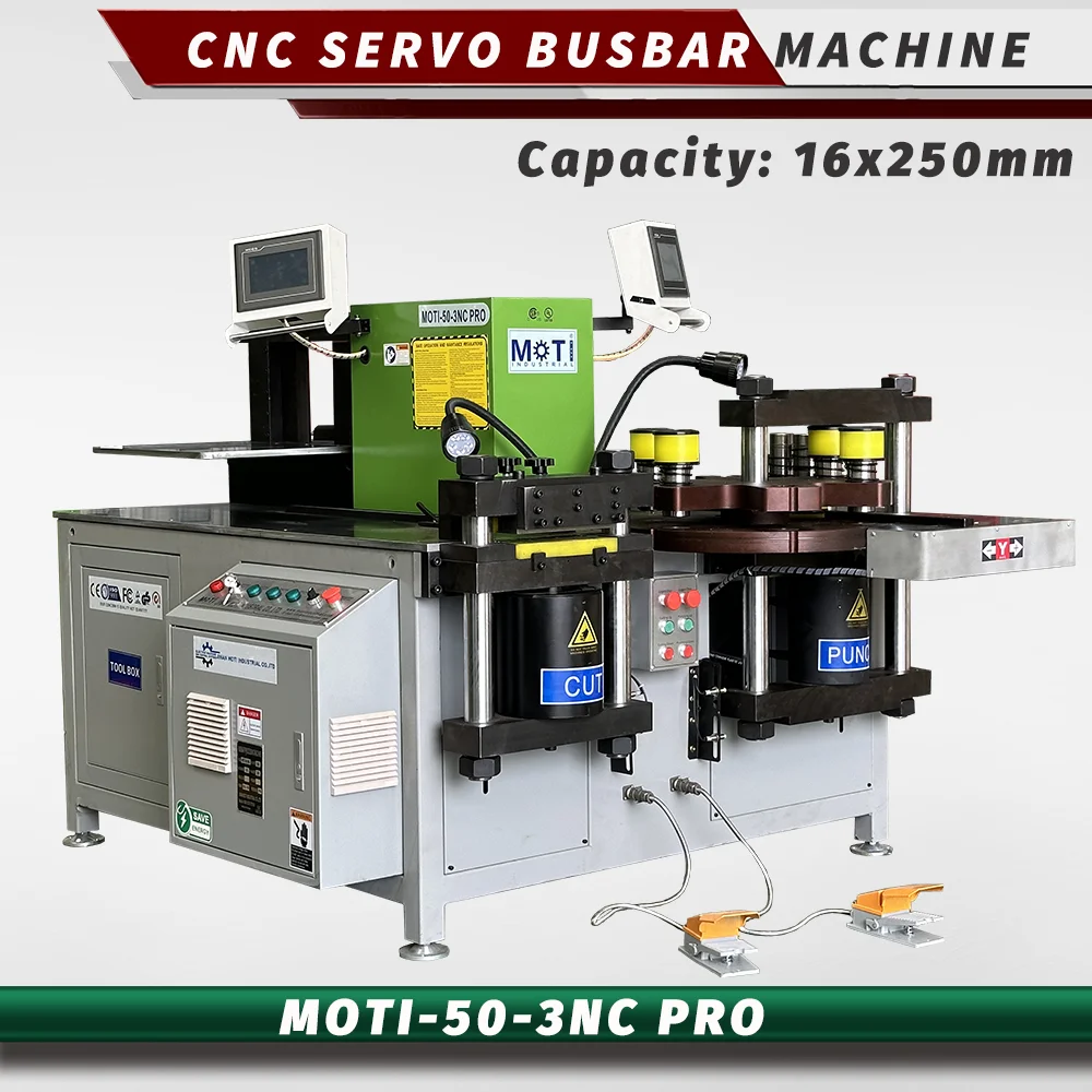
Servo 3-in-1
Four servo positioning axes for repeated work.
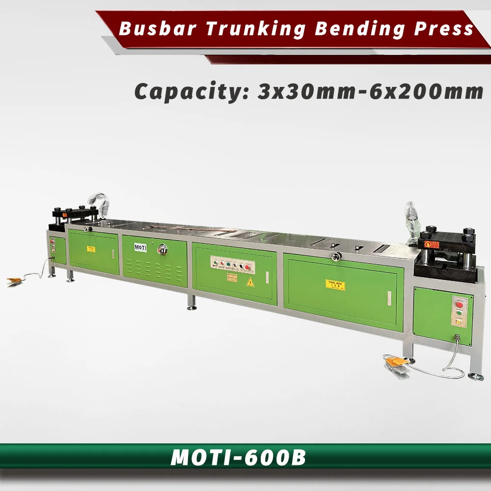
Double-head bending
For busduct connection bars and end forming.
LET’S START WITH YOUR DRAWING
Tell us your material, busbar size and operations.
We’ll help you select the machine and tooling.