Punching: more than the hole diameter
Include the hole shape and size, thickness, material, edge distance and required position. For slots, show the long-axis orientation. The punch diameter range on a machine page is not a promise that every listed diameter can punch the machine’s maximum thickness. The punch, die opening and force requirement must be considered together.
Bending: direction changes the selection
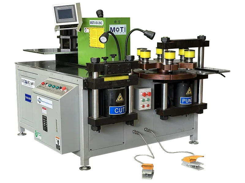
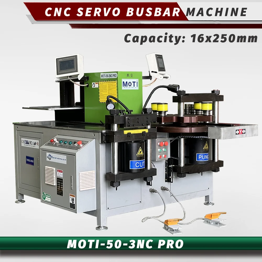
Show whether the bar is being bent across its broad face or on its edge. Include the internal radius, angle, shortest flange and distance to nearby holes. Main-direction and edge-bending capacities differ; the 50-3NC, for example, publishes 16 × 250 mm for the main range and 120 mm width × 12 mm thickness for a 90° edge bend. Use a sketch to remove ambiguity in the direction names.
U and Z shapes need a sequence
A tool that can make one bend may not clear a flange already formed on the same part. Show the whole connection, including offsets and the mating components. Review the order of operations, where the bar is held and whether the tool or machine structure obstructs the later bends.
Embossing, twisting and combined operations
The MOTI range includes tooling discussions for embossing and twisting. The HEMACK project also describes a combined punching and bending tool for breaker connections. Combined tools need a defined part geometry and machine interface; in that example the turret requires custom-machined apertures. An existing standard turret should not be assumed compatible.
Write an itemized tool list
For each tool, record its purpose, size, material range, quantity and machine model. Separate the included package from optional tools and replacement wear parts. The 50-3NC PRO product information lists eight punching-die sets, several bending tools, embossing and cutting blades; the final size list belongs in the quotation.
Make the sample useful for acceptance
Keep the material grade and condition, drawing revision, tool identification and measuring points with the sample. Inspect cut length, hole location, bend angle and final assembly fit. A photograph documents appearance; measured dimensions establish whether the sample meets the agreed drawing.