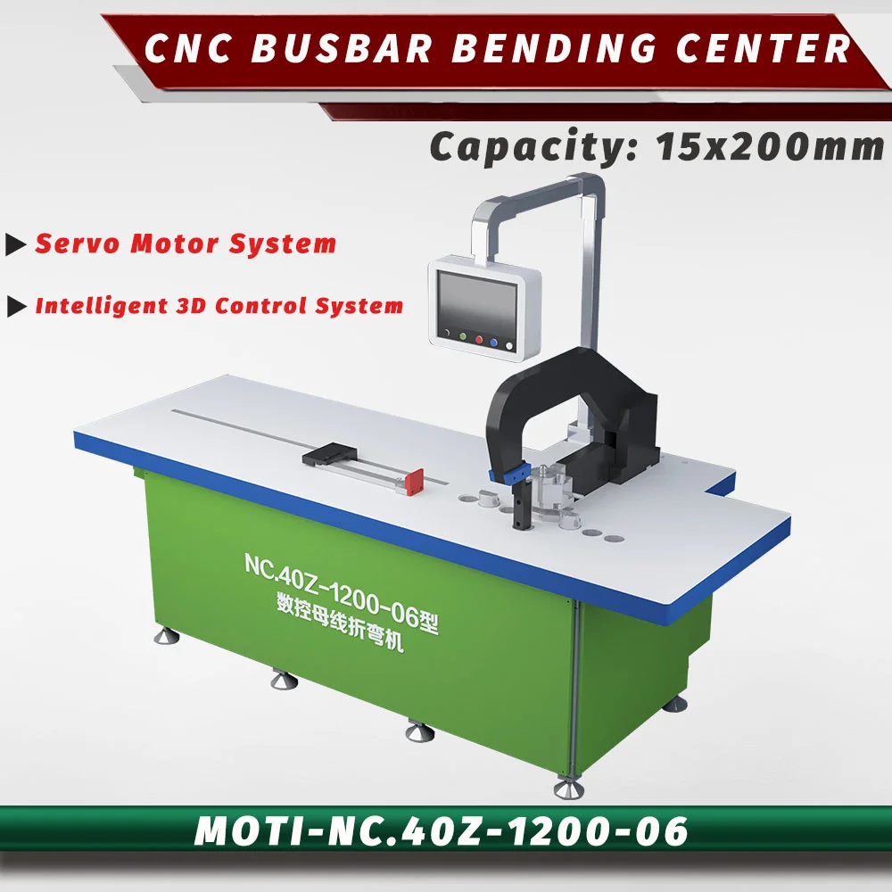
Servo CNC bending center
MOTI-NC.40Z-1200
Dedicated bending with a 160 mm width.
15 × 160 mmThickness × width · operation limits apply
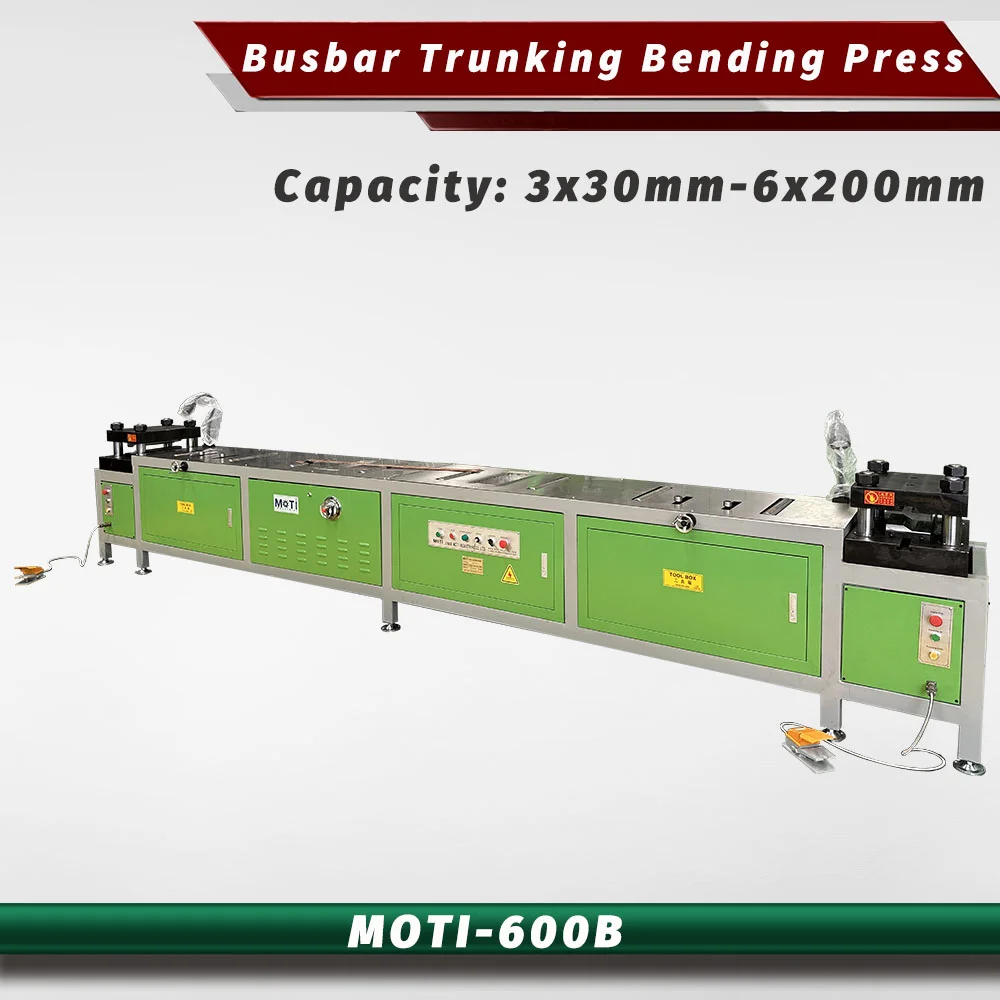
Double-head bending
For busduct connection bars and end forming.
The 600B is a double-head bending machine for busduct connection bars. Its working range is 3 × 30 to 6 × 200 mm. Review both end shapes, their spacing and assembly references before selecting the dies.
Send your drawing to check material, tooling and operation limits.
THE RIGHT APPLICATION
The MOTI-600B addresses connection bars used in busduct and busbar trunking systems. Instead of offering a general cutting, punching and bending workstation, it uses two hydraulic bending heads for forming corresponding ends of a connection. The published range runs from 3 × 30 mm to 6 × 200 mm. It is most useful to evaluate with a complete two-ended connection drawing, including the spacing and relationship between the ends.
01 TECHNICAL OVERVIEW
Machine specifications from MOTI product information. Your quotation defines the supplied version and tooling.
| Thickness × width | 3 × 30 to 6 × 200 mm |
|---|---|
| Machine weight | 1300 kg |
| Motor power | 4 kW |
| Machine dimensions (L × W × H) | 3600 × 1000 × 1500 mm |
| Force (original published unit) | 60 Ton |
| Control | Manual |
02 INSIDE THE PROCESS
Equipment details, positioning and the workpiece requirements to discuss for this model.
The product describes forming two bends at each end using the double-head arrangement. The tool design defines the finished offset. Review both ends together: a correct individual bend is insufficient if the relative end positions do not match the assembly.
Provide thickness, width, total finished length, offsets, angles and internal radii. Show the mating assembly or connection detail when that controls fit. For unusually short parts or conflicting bend directions, a drawing review is needed before a tooling proposal.
The published control description is manual, with hydraulic operation at the two ends. Single-operation forming does not mean automatic loading and unloading. Include placement, removal and dimensional inspection in the demonstration.
03 TOOLS & FINISHED PARTS
The final tool package follows your part geometry and the selected machine configuration.
Specify both end shapes and their relationship, with a drawing revision for the sample.
Confirm the supported part-length range and setup method for the proposed connection.
The 600B is a bending machine. Plan upstream cutting and punching separately.
FOR A TOOLING REVIEW
04 FROM SELECTION TO PRODUCTION
A cropped view of one end is not enough to specify a double-head arrangement. Include the complete length and the assembly datums.
Inspect the offset and relative position of both ends after forming. Use the material and thickness intended for production.
The published machine measures 3,600 × 1,000 × 1,500 mm and weighs 1,300 kg. Allow working space around both ends and include the preceding cutting and punching operations in the layout.
05 MOTI-600B · QUESTIONS
Its supported product application is double-head bending. A generic force-table label does not make it a 3-in-1 machine.
The 600B is focused on paired end forms for busduct connections. A changing mix of complex busbar shapes may require a different bending process and tool arrangement.
The published thickness range is 3–6 mm, paired with widths from 30–200 mm. Have the complete size and shape combination reviewed for the proposed tools.
06 COMPARE OPTIONS
Servo CNC bending center
Dedicated bending with a 160 mm width.
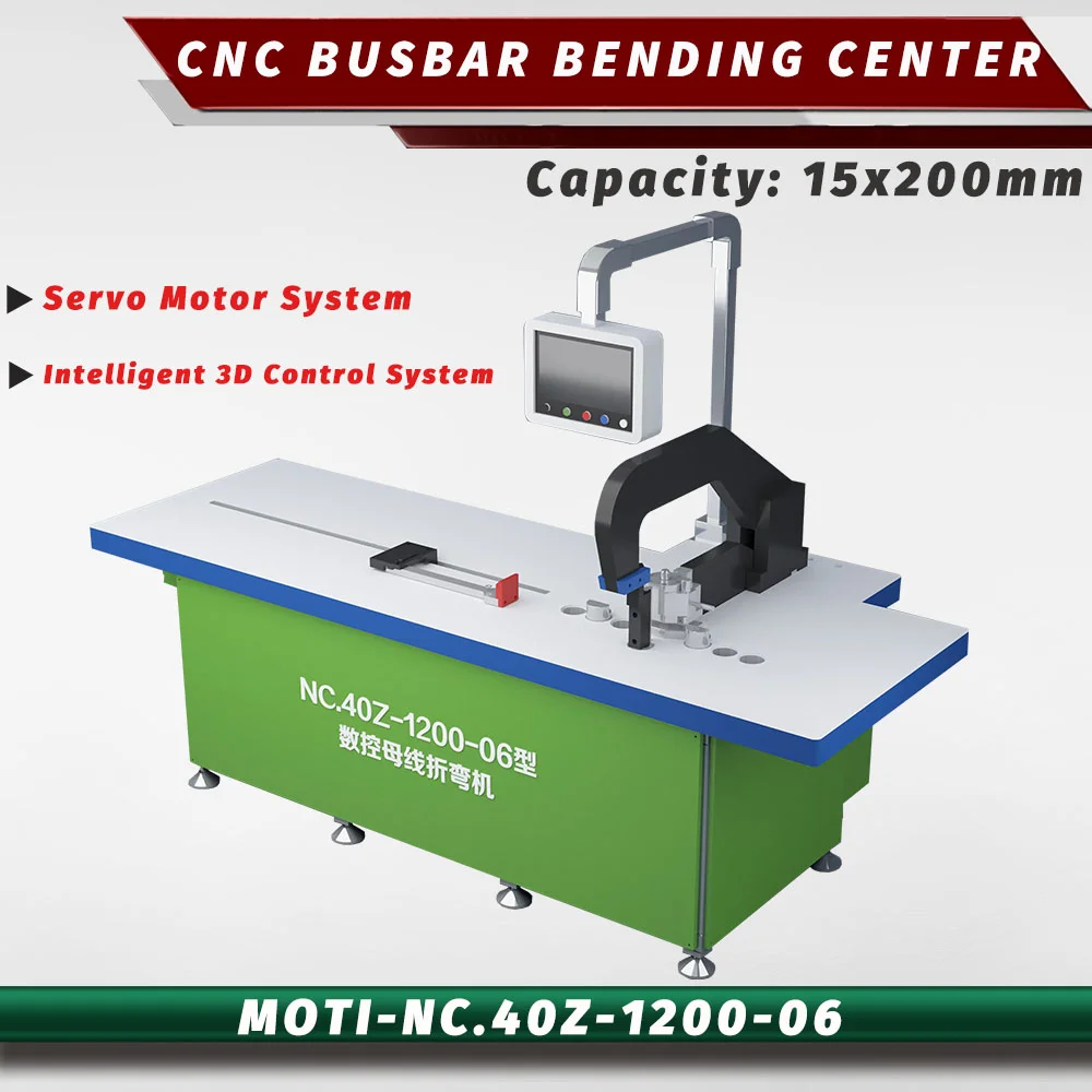
Servo CNC bending center
Dedicated bending with a 200 mm width.
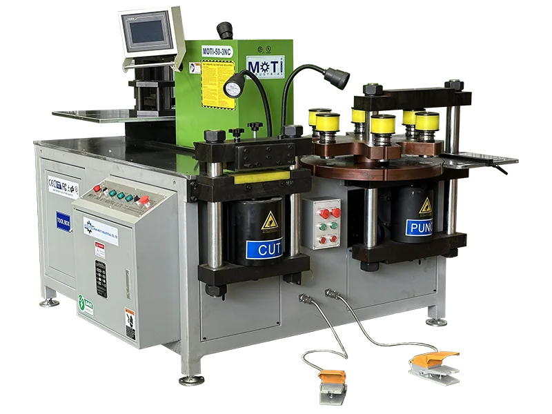
3-in-1 workstation
A wider working range for panel production.
LET’S START WITH YOUR DRAWING
Tell us your material, busbar size and operations.
We’ll help you select the machine and tooling.