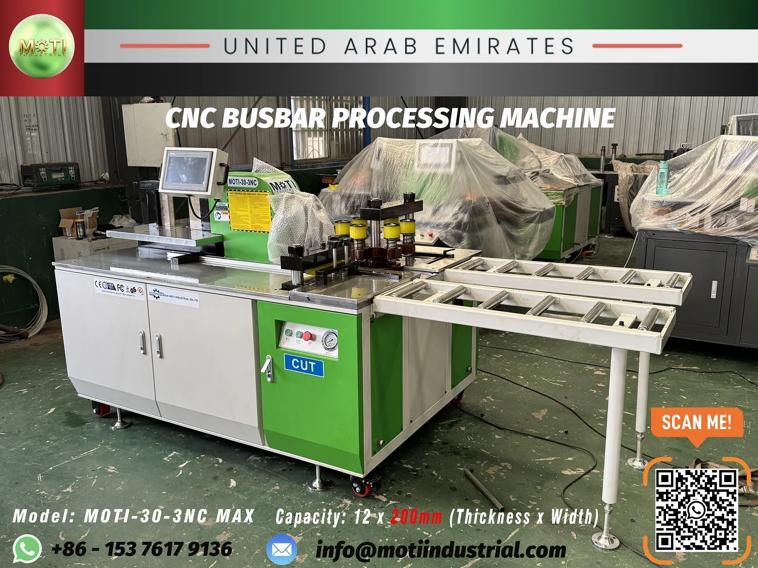
Wide-format 3-in-1
MOTI-30-3NC MAX
More width in the 12 mm thickness class.
12 × 200 mmThickness × width · operation limits apply
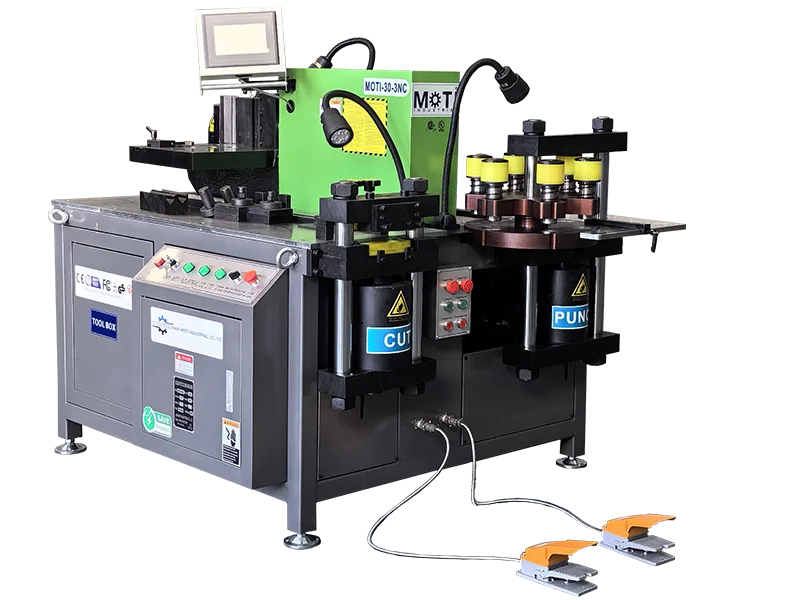
3-in-1 workstation
Everyday busbar fabrication for panel workshops.
Start with the 30-3NC when your copper busbar work fits the 12 × 160 mm range and you need cutting, punching and bending at one workstation.
Send your drawing to check material, tooling and operation limits.
THE RIGHT APPLICATION
The MOTI-30-3NC brings cutting, punching and bending into one workshop machine for copper busbars up to 12 mm thick and 160 mm wide. It suits a production mix with changing connection lengths and hole patterns. Our Vietnam delivery is an example of this model supplied to a switchgear manufacturer. If width is the limiting dimension, compare the 12 × 200 mm MAX before moving to a higher thickness class.
01 TECHNICAL OVERVIEW
Machine specifications from MOTI product information. Your quotation defines the supplied version and tooling.
| Thickness × width | 12 × 160 mm |
|---|---|
| Punching force | 300 kN |
| Bending force | 300 kN |
| Machine weight | 1450 kg |
| Bending accuracy | ±1 ° |
| Repeat bending accuracy | ±0.3 ° |
| Machine dimensions (published order) | 1790×1400×1420 mm |
| Punching diameter | 4.3–25 mm |
| Main motors | 3 × 4 kW |
| Edge bending (width × thickness) | 100 × 10 mm |
02 INSIDE THE PROCESS
Equipment details, positioning and the workpiece requirements to discuss for this model.
The hydraulic shearing station has a published 12 × 160 mm thickness × width range. Its cutting structure supports preparation of blanks for punching and bending. Review the blade arrangement, length reference and support of the offcut with your actual bar; check cut squareness and edge condition on a sample before continuing to the next operation.
The punching station uses a six-position turret so several commonly used dies can remain installed. The published hole-diameter range is 4.3–25 mm. Coordinate, positioning-pin and laser positioning methods are described for the series; specify the required arrangement in the quotation. Each die must be matched to the material and thickness—maximum bar capacity does not mean every small punch works at that thickness.
The 30-3NC product information shows closed and open bending arrangements; specify the version you need. Digital angle control supports repeat work. Appropriate tools extend the work to flat, edge, U and Z forms, with embossing and twisting configurations to discuss. The main-direction 12 × 160 mm rating differs from the edge-bending limit shown in the specifications. Set up and check the tool around the complete shape, especially short flanges and successive bends.
03 TOOLS & FINISHED PARTS
The final tool package follows your part geometry and the selected machine configuration.
Specify each hole shape, size, quantity and required thickness. Include slot orientation and edge distance.
Define flat or edge bends, angle, radius, minimum flange and any U/Z sequence. The finished shape determines tool access.
Confirm the blade set for the selected machine and material; include replacement blades if needed.
Twisting, embossing or combined operations need a drawing and confirmation of the machine interface.
04 FROM SELECTION TO PRODUCTION
Identify the material, drawing revision and finished-part dimensions. Select the required punch and bending tools, set the cutting reference and provide support for the full bar length. Use the operating manual for setup and tool changes.
Check cut length, hole centers and the finished bend against the drawing. Keep the same datum through successive operations. For a new material batch or tool, check the first bend before applying the setting to the rest of the order.
The three independent hydraulic workstations allow cutting, punching and bending to be organized in parallel. Plan the operators’ working areas, part transfer and material supports. Actual output depends on the whole job, including loading, positioning and inspection.
05 MOTI-30-3NC · QUESTIONS
Its headline working range is 12 × 160 mm. Compare thickness and width together, then check the punching diameter, edge-bending capacity, motor power, footprint and handling space. Those operation-specific limits are more useful than selecting by model number alone.
No. The standard machine requires workpiece handling and positioning at the workstations. CNC bending control and independent hydraulic systems do not make it an automatic production line. For servo-assisted positioning at cutting, punching and bending, compare the 50-3NC PRO.
The standard series distinguishes a published bending accuracy of ±1° from repeat bending accuracy of ±0.3°. These are different measures. Your trial should state the material, tooling, angle and measuring method, and check the completed part.
Yes. Send a dimensioned drawing with material, thickness, bend radius and angle, holes and assembly references. We can discuss the tool design and whether the existing turret or fixture needs a custom interface.
06 COMPARE OPTIONS
Wide-format 3-in-1
More width in the 12 mm thickness class.
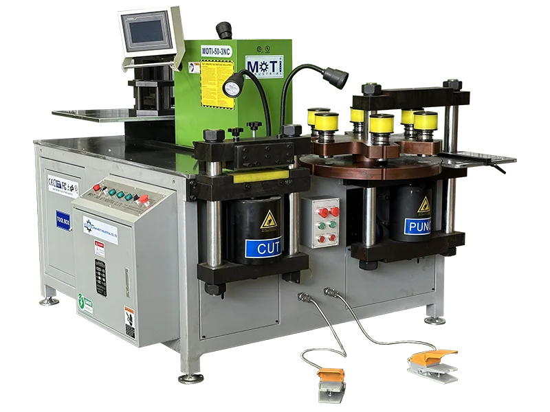
3-in-1 workstation
A wider working range for panel production.
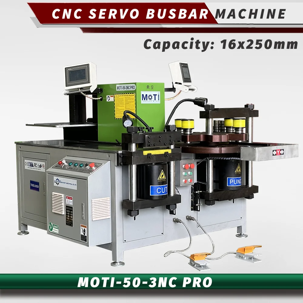
Servo 3-in-1
Four servo positioning axes for repeated work.
LET’S START WITH YOUR DRAWING
Tell us your material, busbar size and operations.
We’ll help you select the machine and tooling.