
By MOTI Industrial · 10 September 2026
A useful busbar hole-pattern drawing tells the tooling reviewer where each hole belongs on the finished connection. Include the hole shape, size and orientation, the reference edges or datums used to locate it, material details and the drawing revision. Show which dimensions apply to the flat bar and which must be checked after bending.
This checklist helps a buyer and drawing owner resolve missing information before requesting a tooling proposal. For the broader choice of punches, bending tools and samples, use the busbar tooling and sample preparation guide.
Give every hole a clear reference
A datum is a specified reference used to locate or measure a feature. On a drawing, “the first hole is near the left end” leaves two questions open: which end is left, and where is the distance measured from? Identify the viewing direction and reference end or edge. Keep those labels consistent in the hole table, finished-part views and inspection notes.
Ask the drawing owner to identify the dimensions that control assembly fit. A hole-to-hole spacing and a hole-to-end distance answer different questions. Both may matter, but the supplier should not have to choose which requirement takes priority when dimensions conflict.
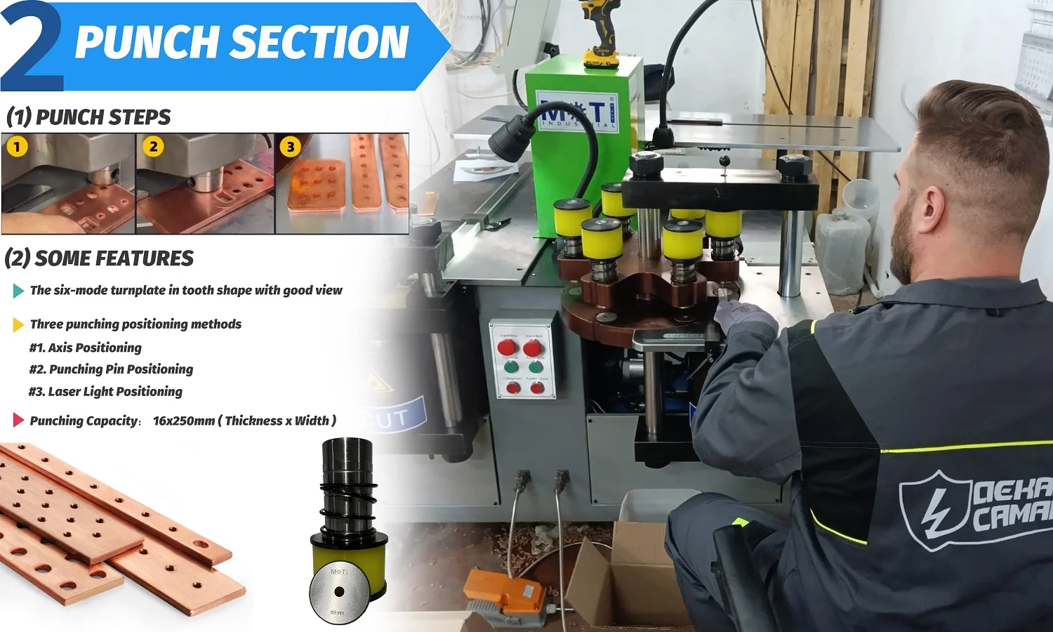
Build a hole schedule that can be checked against the drawing
Use a row for each hole or clearly defined group of identical holes. The table below lists the information to request; the drawing owner supplies the actual dimensions and tolerances.
| Field | What to identify | Ambiguity to resolve |
|---|---|---|
| Part and revision | Part number, revision, units and the governing drawing | A hole table attached to an older drawing |
| Hole reference | A label matching the drawing, plus the number of repeats | A repeated pattern with no defined first position |
| Shape and size | Round diameter, or the full dimensions of a slot or other profile | A slot length that could mean overall length or distance between end-radius centers |
| Location | Coordinates or dimensions tied to the stated reference edges or datums | A center-to-edge dimension being read as the remaining material beside the hole |
| Orientation | Slot direction, viewing face and any rotated or mirrored version | Identical-looking views representing different handed parts |
| Acceptance | Required size and location tolerances, measuring references and the part condition to inspect | A finished-assembly requirement being checked only on the flat blank |
When both a CAD file and a dimensioned document are supplied, identify the revision of each and which document governs if they disagree. Confirm the file format the reviewer can use. Do not silently scale a screenshot or infer a missing dimension from the apparent proportions of a photograph.
Check the viewing face, slots and mirrored parts together
For a straight bar with a symmetrical pattern, orientation may appear obvious. It becomes less obvious when one end has an offset, one slot is rotated, or two parts look alike but fit opposite sides of an assembly. Mark the reference end and viewing face on each variant. State whether it is a separate part number or an explicitly defined mirrored version.
For a slot, show its orientation and how its length is dimensioned. For a repeated row, show the first position, the spacing and the repeat count. If the drawing already contains these details, preserve that convention in the enquiry instead of retyping a partial description that loses the references.
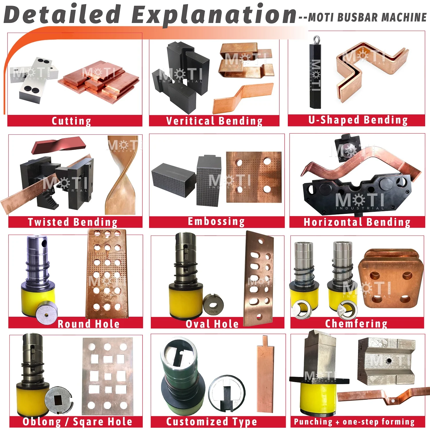
Separate flat-bar locations from the finished connection
Where holes sit near bends, include a finished-part view and label any flat-pattern dimensions separately. Show the relevant bend direction and the hole’s relationship to the mating connection. Ask the supplier to review access and the proposed order of operations against the whole part.
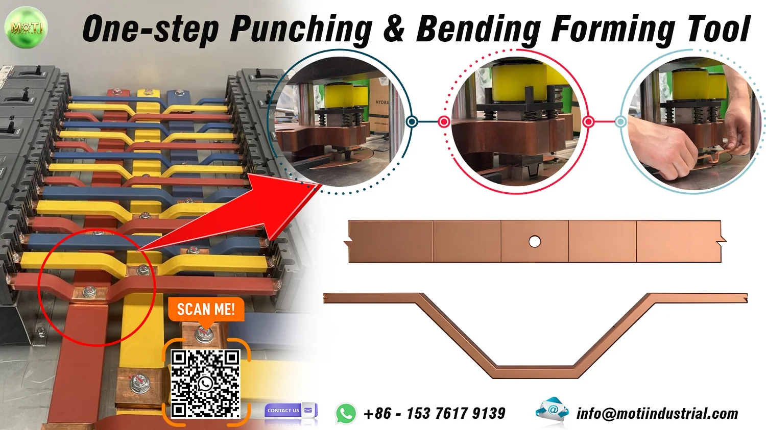
MOTI’s HEMACK connection-tooling project illustrates why this matters: its published combined punching and bending tool requires a drawing that defines thickness, bend angles and openings, together with a compatible, custom-machined turret interface. That example supports reviewing holes and bends together; it does not establish that the same tool fits another connection.
Send the drawing with the material and machine context
Attach the material grade and condition, bar thickness and width, and any specified surface or assembly requirements. For an existing machine, provide its model and tool-interface information. A matching nominal hole size alone does not establish that a replacement punch and die will fit.
The MOTI-50-3NC product page provides an initial equipment reference. Have the supplier confirm the proposed hole shape, material, thickness, position and tooling together. Keep the final tooling list linked to the reviewed drawing and machine configuration.
Close the review with an agreed inspection record
Before a sample is made, record the drawing revision, material, tool identification and dimensions to inspect. Ask the reviewer to list unresolved items explicitly, such as an unclear slot convention, conflicting reference dimensions or missing assembly view. The drawing owner can then answer the actual open points.
Keep the measured sample results with that same revision. Use the tolerances and sampling requirements agreed for the part; a catalogue image or successful demonstration does not supply them. This creates a traceable basis for approving the tool or requesting a specific correction.
For a tooling enquiry, start with the marked drawing, hole schedule and material details. Visit custom busbar punching dies and bending tools for the available review scope, or send MOTI your drawing and open questions.
Sources: MOTI-50-3NC manufacturer information and MOTI’s HEMACK tooling report, checked 9 September 2026. The drawing checklist is practical enquiry guidance, not a universal dimensional or acceptance standard.