
“CNC,” “servo” and “automatic” do not describe the same busbar production process. One machine may control a bending angle, another may position several dimensions, and a punching and shearing center may clamp and process a programmed hole sequence. None of those labels alone tells you who loads the material, moves the part to bending, checks the result or handles an exception.
Compare automation one step at a time. Start with the customer file and follow the material until an inspected part is ready for assembly. For every step, record what the software controls, what the machine moves and what the operator still does.
Write the complete part route first
Choose one representative order and list its path: receive the drawing, confirm the revision, prepare the program, select tools, load stock, establish the datum, cut, punch, transfer, bend, unload and inspect. Add changeover, tail material and recovery from an interrupted job.
This route creates a common comparison. A faster automated position can be valuable, but it should not hide manual preparation or transfer elsewhere. The complete production-trial method shows how to time preparation, stable running, inspection and recovery separately.
Level 1: controlled motion is narrower than an automated line
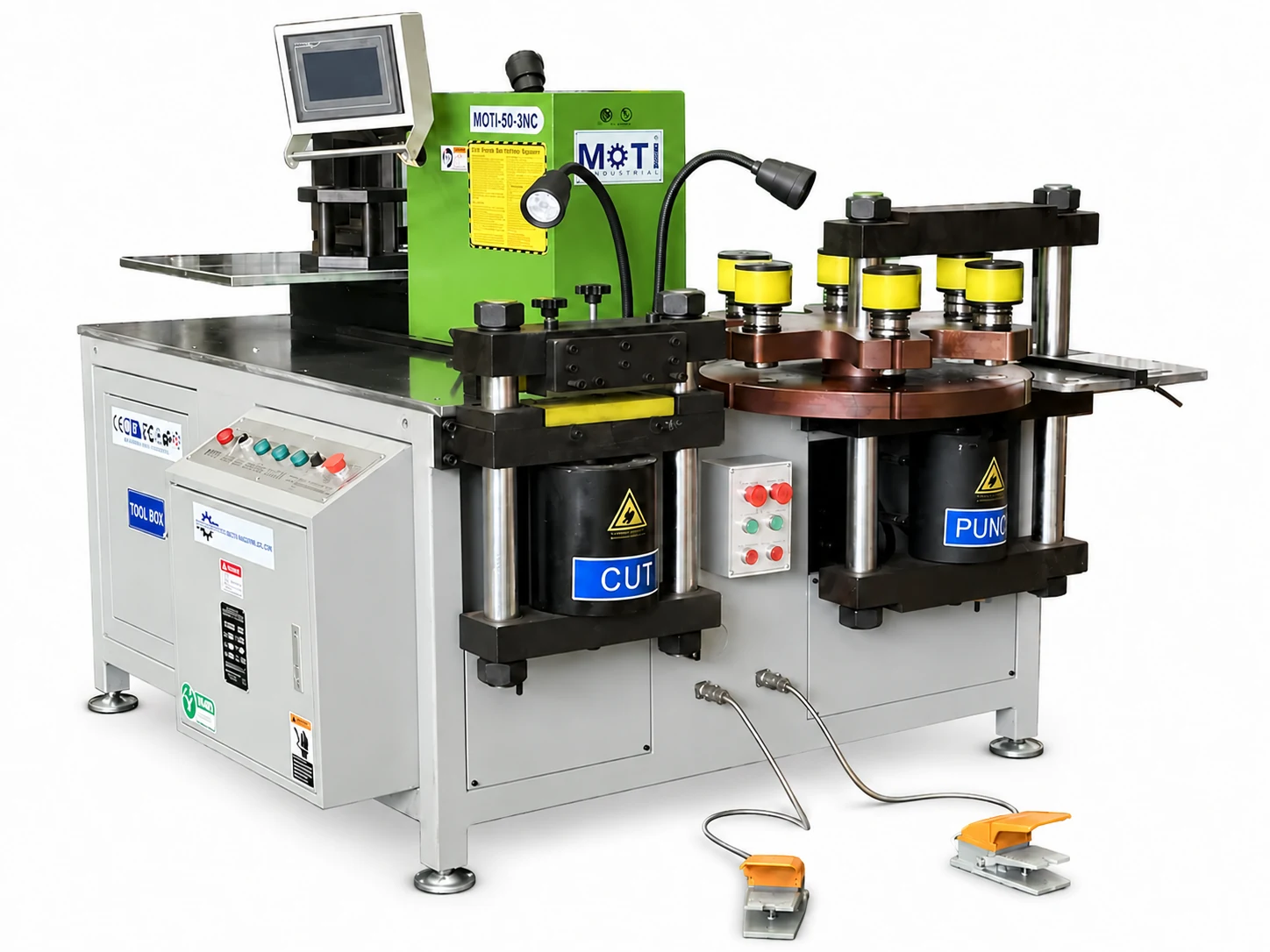
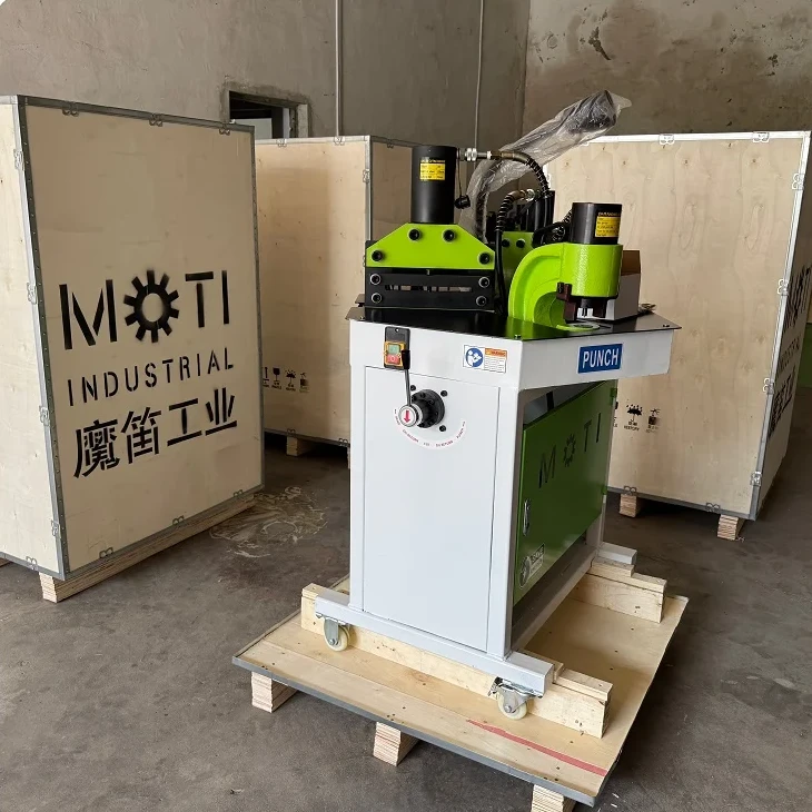
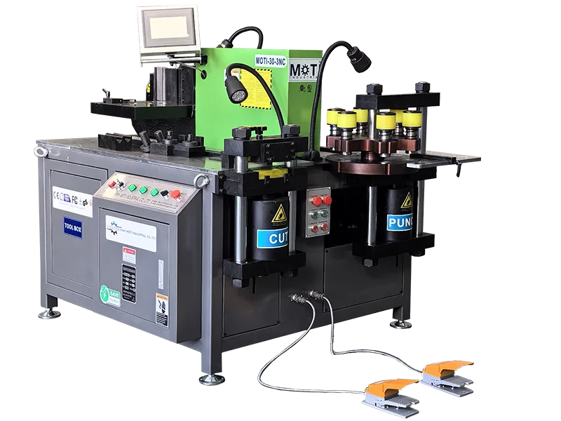
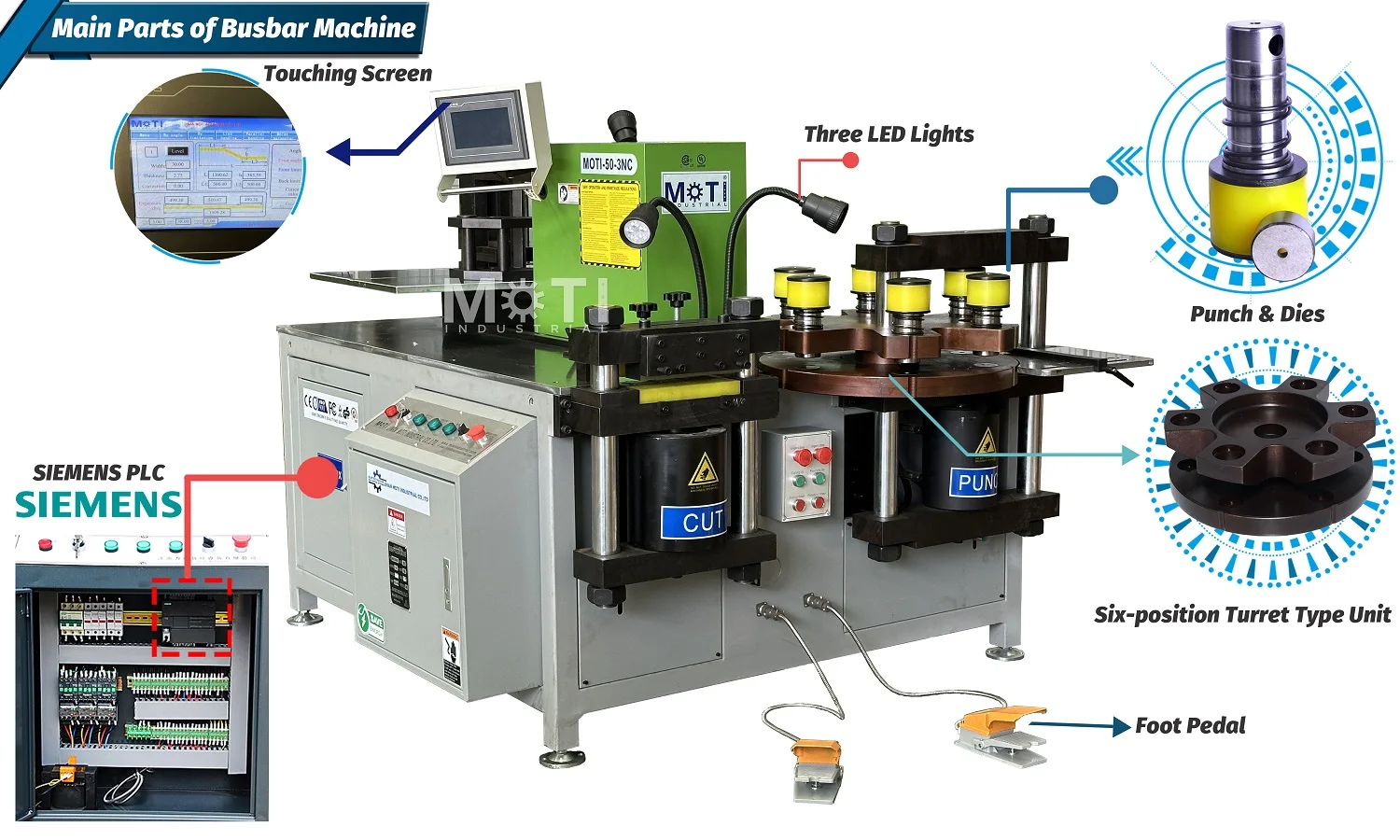
A standard three-in-one busbar machine brings cutting, punching and bending into one workstation. Depending on the selected configuration, a control can assist the bending angle or another defined machine movement. The operator may still measure or set a reference, move the workpiece among stations, choose or change tools, remove the part and inspect it.
Ask the supplier to name the controlled variable. “CNC bending” should be translated into a specific input, feedback or movement that can be demonstrated. It should not be expanded into automatic feeding for the cutting and punching stations unless those functions are included in the actual configuration.
Level 2: servo positioning automates defined dimensions
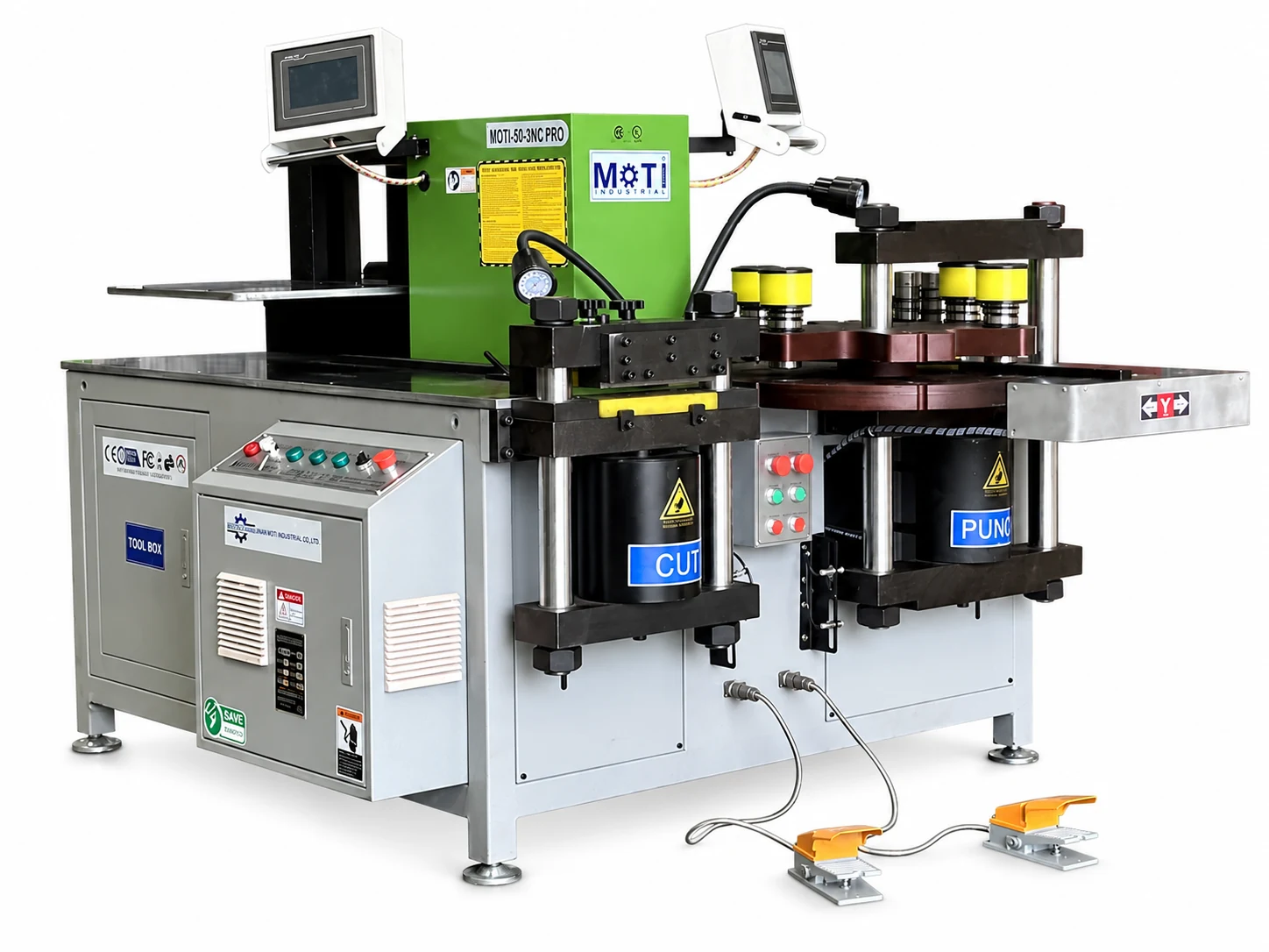
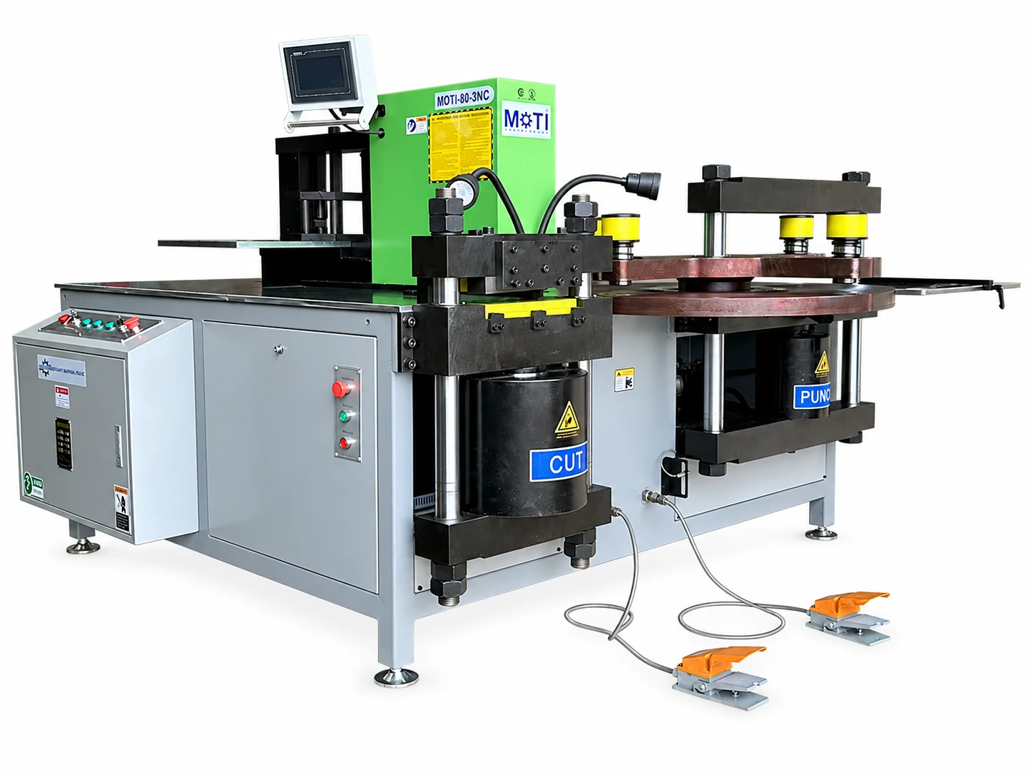
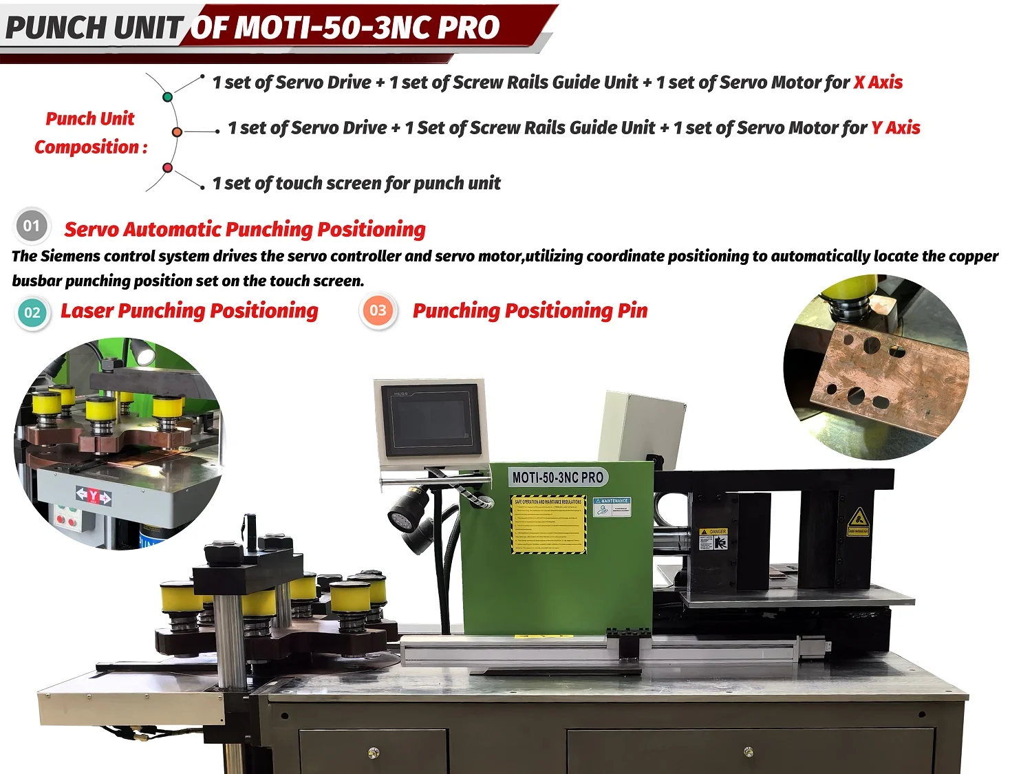
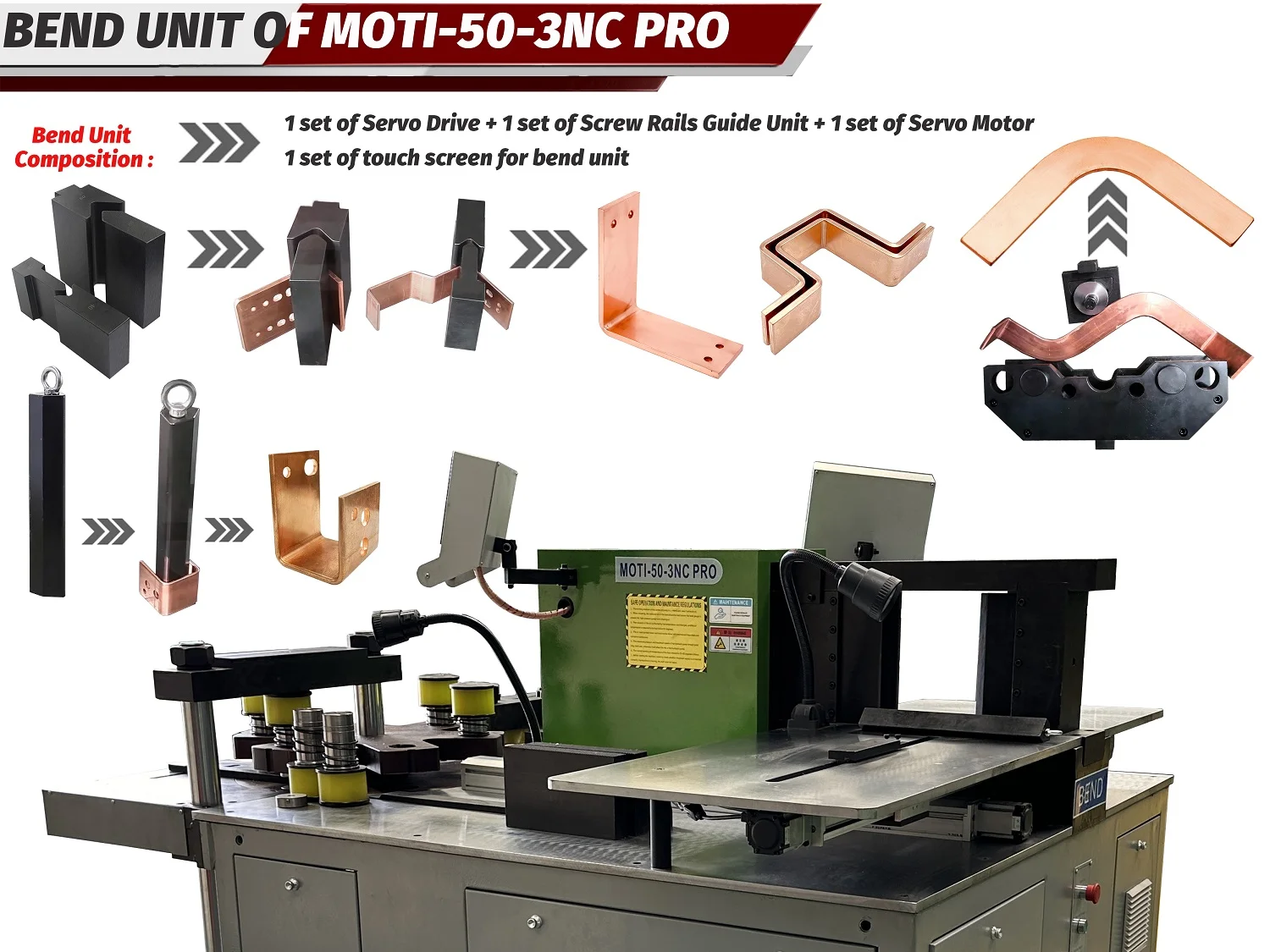
A servo axis can move a gauge or coordinate to a programmed position. The MOTI-50-3NC PRO product information lists four positioning axes: cutting X, punching X/Y and a bending backgauge. This is more specific than a general “servo machine” claim.
Check the travel of each axis against the actual parts, then demonstrate the first part, several repeats, a change to another job and a return to the first job. Also record the manual steps before and after each position. Servo positioning does not establish automatic loading, station transfer, tool changes, unloading or inspection.
The servo positioning trial guide provides a part-based method for mapping drawing dimensions to cutting, punching and bending references.
Level 3: automatic punching and shearing controls a longer sequence
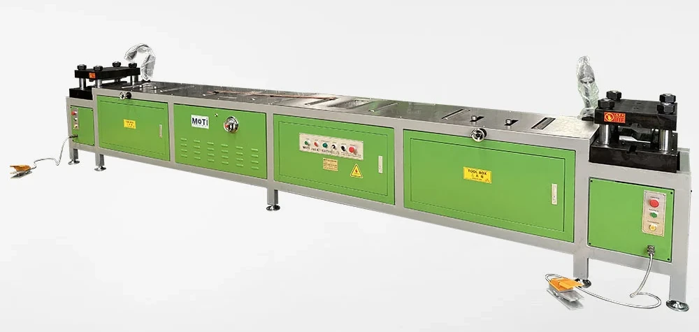
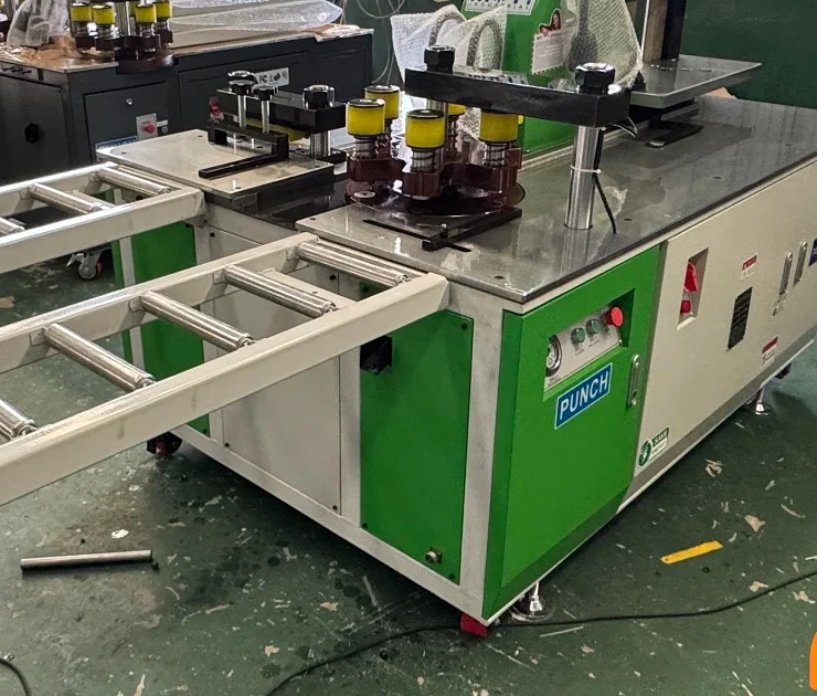
An automatic punching and shearing route can add programmed clamping, re-clamping, hole sequencing and cutting. The MOTI product page for this route describes automatic clamping and re-clamping, with tool arrangements such as six punches plus cutting and embossing, or eight punches plus cutting. The page number used in the internal record is not a verified model name, so the final quotation must identify the exact machine and capacity.
Test the sequence with the intended stock length, part layout, hole shapes and minimum finished part. Watch what happens at the clamp zone, during re-clamping, at the final cut and when the tail is removed. Confirm whether loading, discharge or collection equipment is included or optional. A programmed punching rate is not the same as inspected finished parts per hour.
Level 4: a CNC bending center automates a dedicated bending workflow
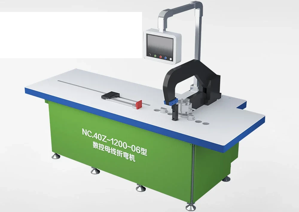
A dedicated bending center can connect part data, bend sequence and controlled positioning around the bending operation. It should not be compared as if it also punches and shears. The MOTI-NC.40Z-2000 page describes CAD/CAM functions for modelling, changing dimensions and generating punching, shearing and bending files, while the machine itself is presented as a dedicated bending center.
Use the buyer’s real file to demonstrate import or entry, unfolding, bend order, interference review, program change and recovery. Confirm supported formats, software version, licence, language, backup method and training in writing. A reference to 3D or CAD/CAM does not prove connection to every CAD, EPLAN, ERP or MES environment.
Level 5: design-to-production coordination is a data project
The highest automation discussion often begins before the machine. Engineering and production may want one revision to flow through unfolding, nesting, punching, shearing and bending. That requires agreement on file ownership, revision control, tool libraries, machine programs and the response to a changed drawing.
Map every data handoff. Record who approves the source drawing, which software creates each program, how machines receive it, and how a corrected version replaces the old one. The drawing revision control guide helps keep the drawing, tools, programs, samples and results aligned.
Keep material handling and inspection inside the boundary
Automation claims are incomplete if the free end of a long busbar still needs support, a person must carry the blank to bending, or finished parts wait for manual identification. Use the material-handling workflow guide to mark loading, support, rotation, transfer, unloading, offcuts and work in progress.
Inspection also remains part of production. Define which dimensions are checked, when the first part is approved, how repeat parts are sampled and what happens after a failed result. Unless an inspection system is explicitly included and demonstrated, do not describe the line as automatically delivering accepted parts.
Compare quotations with an automation boundary table
Use one row for each step and require four answers: input, machine-controlled action, operator action and acceptance evidence. Add the supplied hardware, software, tool set, loading or unloading option, training and interface responsibility. Then run the same order through each proposed configuration.
The fixed standard-versus-servo guide helps compare positioning choices. Extend that method when evaluating automatic punching and shearing or a coordinated bending cell.
Send MOTI one representative drawing or production file, the material sizes and stock length, batch quantity, current process and the manual step you most want to reduce. We can mark the proposed control, positioning, handling and inspection boundaries before arranging a demonstration.
Sources: MOTI standard, servo-positioning, automatic punching and shearing, CNC bending and production-planning records, checked 23 September 2026. Exact automation scope depends on the quoted machine, software, tooling and options; no universal output or interface compatibility is claimed.