
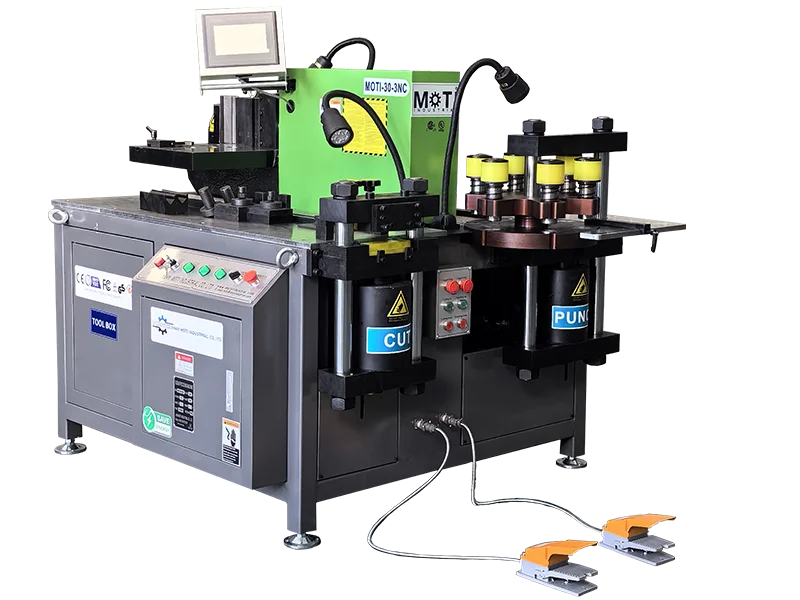
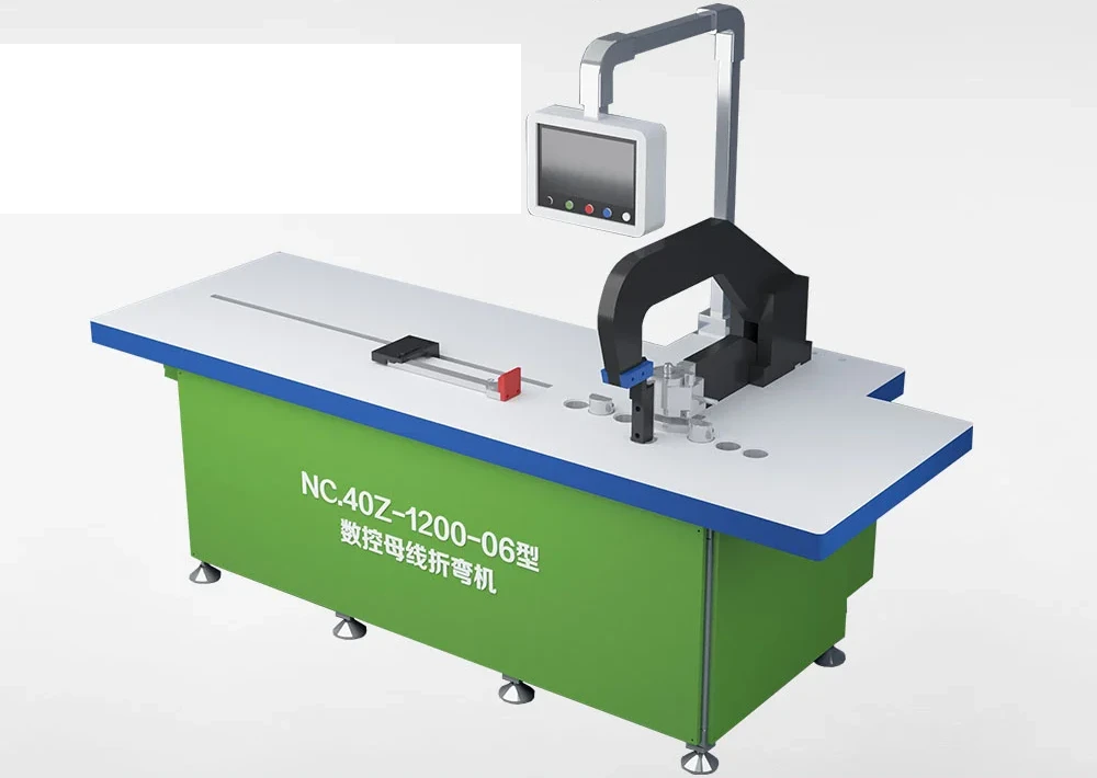
A busbar machine can fit the required copper thickness and width while the surrounding workflow still creates delays, handling risk or inconsistent positioning. Long stock must move from storage to the first operation, remain supported during cutting or punching, transfer between stations, and leave the work area as finished parts and offcuts.
Include that movement when comparing equipment. Start with an actual part route and identify every point where an operator lifts, pushes, rotates, repositions or waits for material. The result is a more useful equipment specification than a machine-capacity table alone.
Map the route before choosing the machine location
Draw the route from raw-stock storage through cutting, punching, bending, inspection and the next production step. Record the common and maximum stock lengths, thicknesses and widths, plus the range of finished-part sizes. Separate copper, aluminium and any round-bar work because their support and tooling conditions may differ.
Mark doors, columns, fixed benches, electrical cabinets, guarded areas and the paths used by people or lifting equipment. Leave room for the material beyond the machine footprint. A long busbar can sweep a much larger area when it is rotated or moved from one station to another.
The busbar machine selection guide begins with representative parts. Add the physical route for those same parts so that capability and handling are assessed together.
Specify supports as part of the working configuration
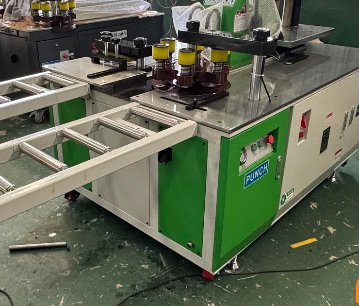
A quotation that lists only the machine can leave the stock-support method undefined. For each operation, state the required support length, working height, adjustment range, roller or surface arrangement, quantity and location. Confirm whether the supports are included, optional or supplied by the buyer.
Support should keep the workpiece stable without changing the intended datum or forcing the operator to hold one end at an angle. For cutting, unstable support can affect the position presented to the stop or gauge. For punching, the material must reach the required hole positions while remaining controlled. For bending, the part needs space for its starting shape and formed shape.
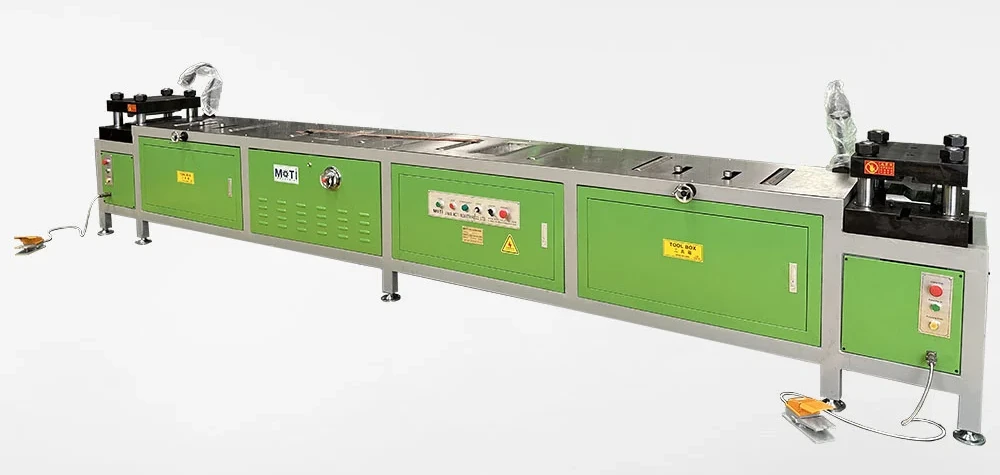
Do not infer a complete handling solution from one catalogue photograph. Check the actual support dimensions, load basis, adjustment and machine interface in the quotation and order documents.
Separate machine positioning from material handling
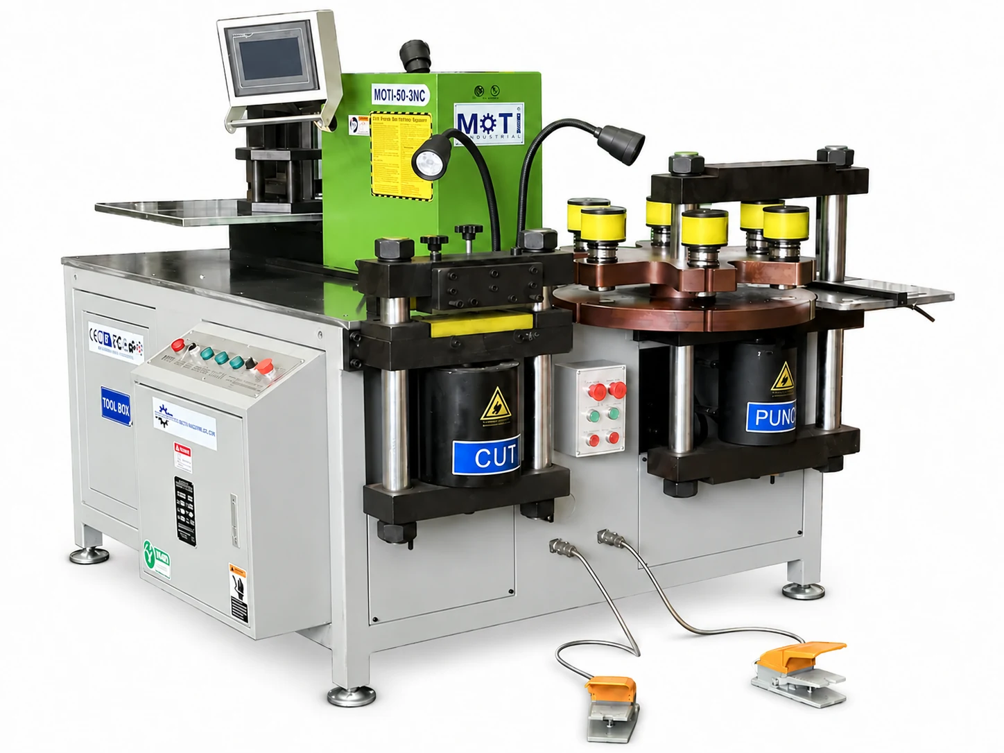
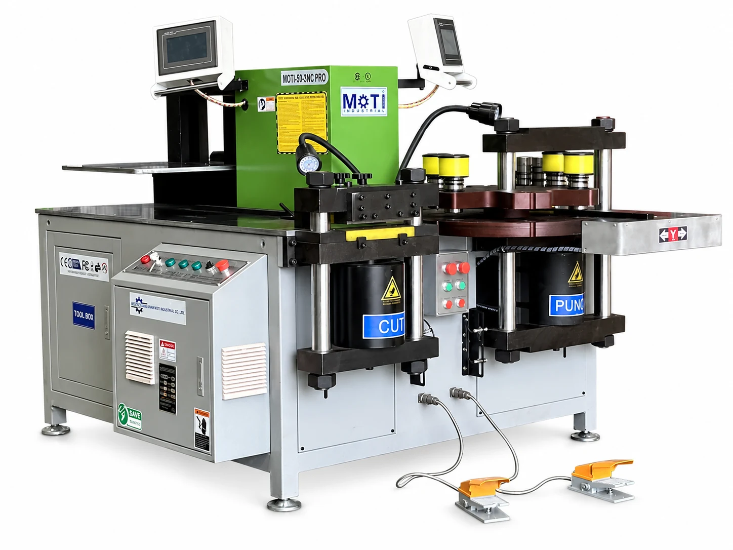
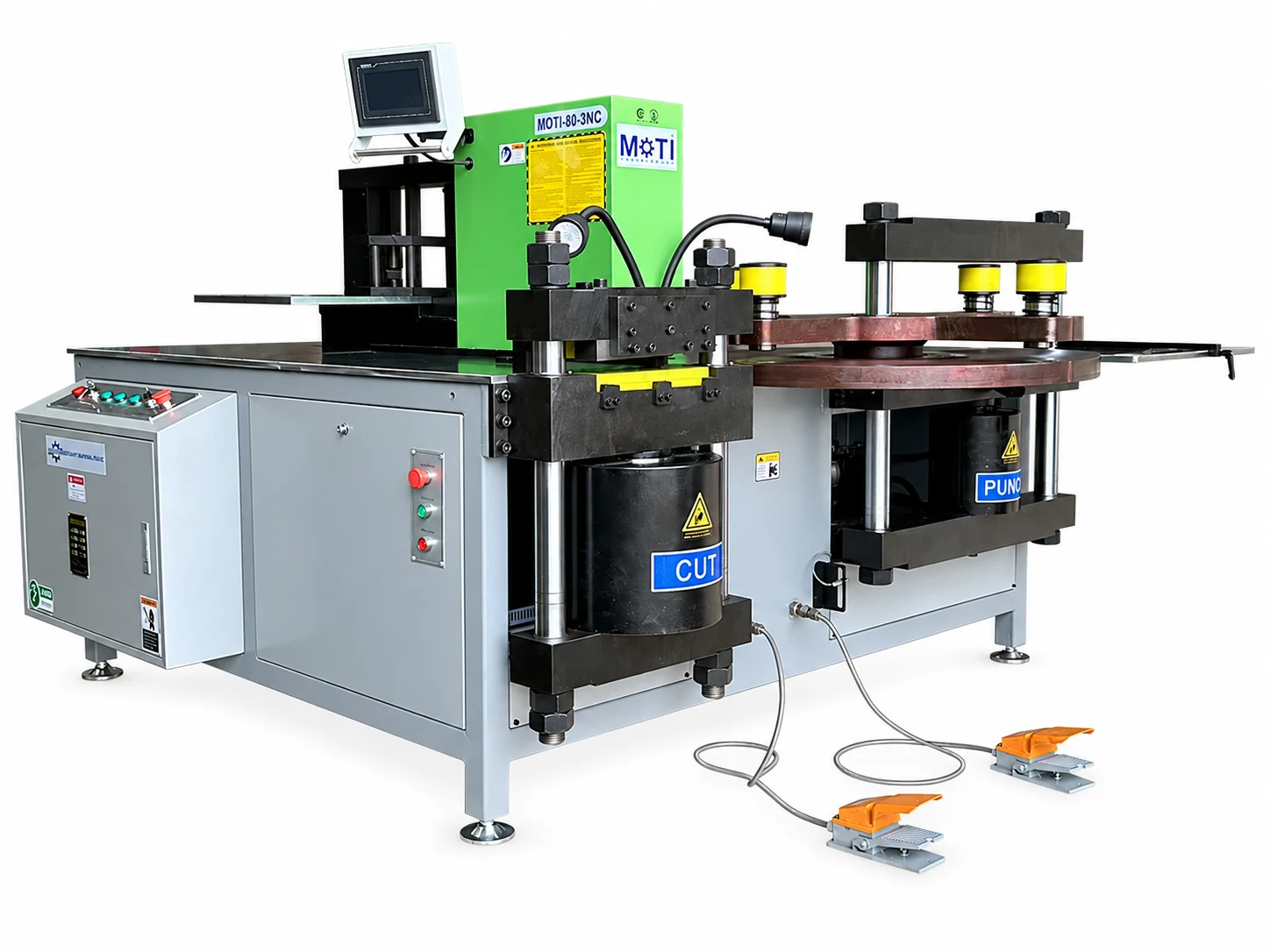
A CNC axis, servo gauge, locator or laser reference can position a dimension, but it does not automatically load raw stock, support the free end or transfer the part between operations. Standard three-in-one machines commonly require the operator to move the workpiece among cutting, punching and bending stations.
Write one line for every manual action: bring stock to the table, align the datum, support the free end, rotate or turn the workpiece, move to the next station, remove the finished part and place the offcut. Then identify which positioning actions are controlled by the selected machine version.
This distinction also applies to automatic punching and shearing equipment. A programmed clamp and re-clamping sequence does not establish that loading, unloading or transfer to a separate bending machine is automatic. Any loading or unloading option should be named and demonstrated as part of the exact configuration.
Check transfers between cutting, punching and bending
Use the representative drawing to follow the part through every station. Ask whether the longest raw bar can approach the first station, whether the cut blank can be turned safely, and whether a formed part can leave the bending area without hitting a support, guard or nearby workstation.
For wide or heavy workpieces, record the number of people and handling aid used during the trial. The heavy busbar solution guide explains why thickness, width and bending direction must remain separate. A model such as the MOTI-80-3NC can be evaluated with the actual long-stock support and station-transfer method rather than by its published working ranges alone.
Finished bends can occupy more space than the flat blank. Include the bent envelope, orientation changes and a protected place for accepted parts so that finished surfaces and measured features are not damaged during stacking.
Test shared handling in parallel-station layouts
Adding another work station can reduce one queue while creating another at loading, support or inspection. If two operators work in parallel, show where each person stands, how material enters each station, where completed pieces leave, and whether either route crosses the other.
The UAE custom machine shown below used two punching stations and roller supports for a specific process. The configuration is evidence that stations and supports can be planned together; it does not prove that every two-station layout doubles output.
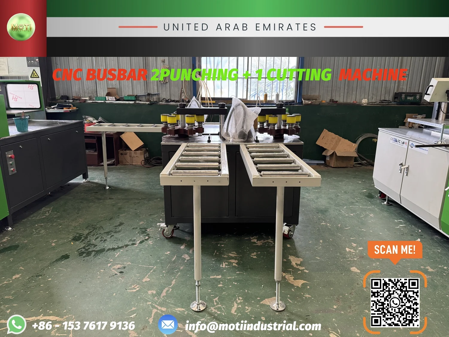
The double-punch workflow guide describes how to test the bottleneck with the same parts, tools and staffing instead of multiplying an isolated machine rate.
Include finished parts, offcuts and work in progress
Plan separate locations for raw stock, identified blanks, completed parts, rejected samples and reusable offcuts. Preserve drawing revision and material-batch identity while work moves between operations. A part waiting for bending should not be confused with a finished part simply because cutting and punching are complete.
Record how short pieces and tail material are removed from the work area. For an automatic punching and shearing route, include re-clamping, final-part discharge and tail handling in the trial. For a three-in-one route, include each transfer and the time needed to restore the next datum.
Measure a complete part, not an isolated stroke
Start the trial when identified stock is collected and end when the finished part is inspected and placed in its next location. Record loading, positioning, tool changes, cutting, punching, station transfer, bending, unloading and inspection separately. Repeat with a normal part and a difficult long or wide part.
The complete production-trial method helps separate preparation, stable running and recovery. A punch count or axis speed cannot represent finished parts per hour when material handling and inspection remain outside the measurement.
Put handling items into the quotation and site plan
List every supplied roller table, support, stop, handling accessory and separate control item. Record dimensions, quantity, adjustment, packing and installation responsibility. Show the agreed machine orientation and working clearances on a simple site sketch, then confirm unloading, movement into position and connection responsibilities.
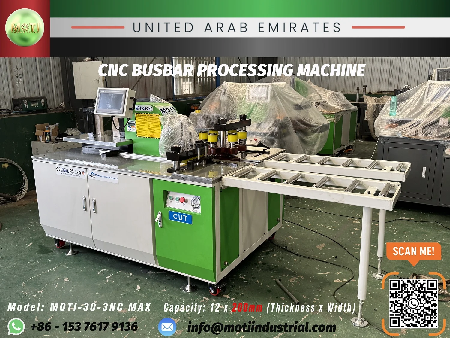
The quotation-scope comparison provides a structure for marking handling items as included, optional, buyer-supplied or excluded.
Send the workflow with the machine inquiry
Send MOTI representative drawings, material sizes and lengths, batch information, current layout and the handling step that causes the most difficulty. Include photos or a simple floor sketch where useful. We can compare the machine, supports and operator route against the same defined workflow.
Sources: MOTI product, project, trial and material-handling records, checked 21 September 2026. Published project images illustrate specific configurations and do not define universal capacity, support quantity, output or safety clearance.