
Adding a second punching station can be useful when punching is the measured constraint in a busbar workshop. It is not an automatic route to twice the output. The result depends on the hole mix, tool allocation, operators, material handling and the operation that receives the punched bars next.
Before asking for a custom configuration, map one representative shift. Record the jobs released, good parts completed, total holes, hole types, tool changes, marking and positioning time, queue time and interruptions. This separates a persistent punching bottleneck from a busy day caused by missing drawings, late material or rework.
Prove that punching is the constraint
Start with the work queue, not the machine brochure. If bars wait consistently for punching while cutting or bending has available capacity, the punching station may be limiting flow. If the whole line waits for drawings, inspection or a crane, another punching head will not remove that delay.
Use the same complete-part timing method described in the busbar production trial guide. Count setup, locating, handling and inspection as well as the hydraulic stroke. For a mixed-order workshop, repeat the check across several common batches instead of timing only the easiest part.
Allocate tools and jobs before choosing two stations
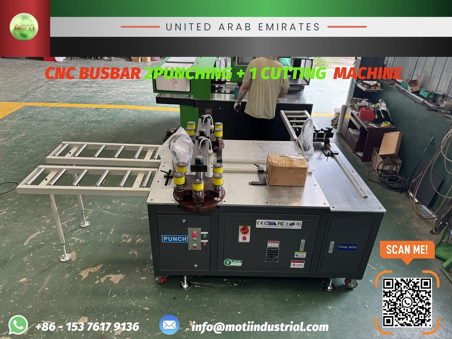
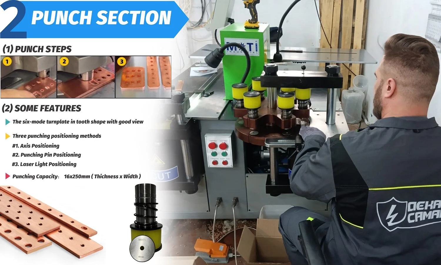
Two stations can remove repeated tool changes when the hole family has a stable pattern. One approach is to assign common round holes to one turret and slots or less frequent sizes to the other. Another is to dedicate each station to a product family. The correct split comes from the actual hole schedule.
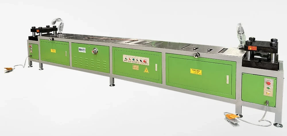
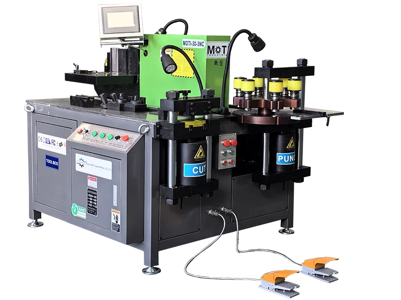
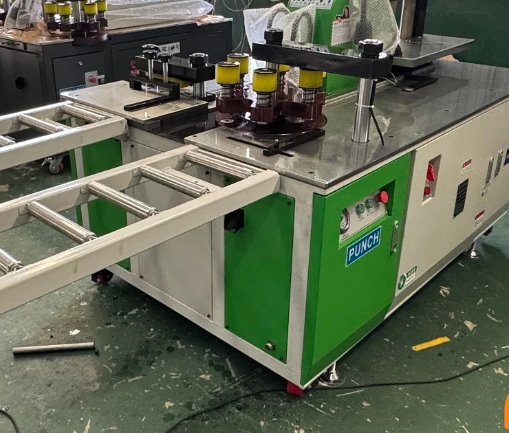
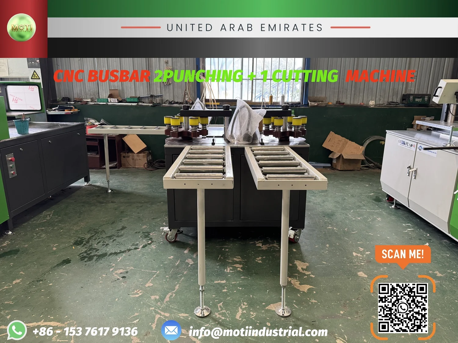
MOTI's published UAE configuration used two six-die punching turrets, one cutting station, three independent power units and three removable levelling roller supports. The published working range was 12 × 160 mm and control was manual. Those facts describe that project only. The supplied dies, openings and locating method for a new order must be checked separately.
A current hole-pattern drawing checklist helps organize datums, mirrored orientation, slot direction and the relationship between flat and formed views. Convert that drawing information into a hole-frequency table before deciding which tools belong at each station.
Check whether two operators can work without creating interference
Parallel stations need a safe and workable division of labour. Confirm how raw bars reach each roller support, where completed bars wait, how long parts turn or cross the aisle, and who performs inspection. If both operators share one handling device or repeatedly enter the same space, the theoretical overlap may disappear.
The same check applies when one operator is expected to serve both stations. Measure walking, loading, positioning and unloading rather than assuming the operator can keep two stations continuously busy. A layout drawing with bar lengths and aisle clearances is more useful than a simple machine footprint.
Compare three configurations with the same parts
A fair comparison uses the same drawings, material, batch sizes and acceptance checks for each route.
| Configuration | When to investigate it | Evidence to request |
|---|---|---|
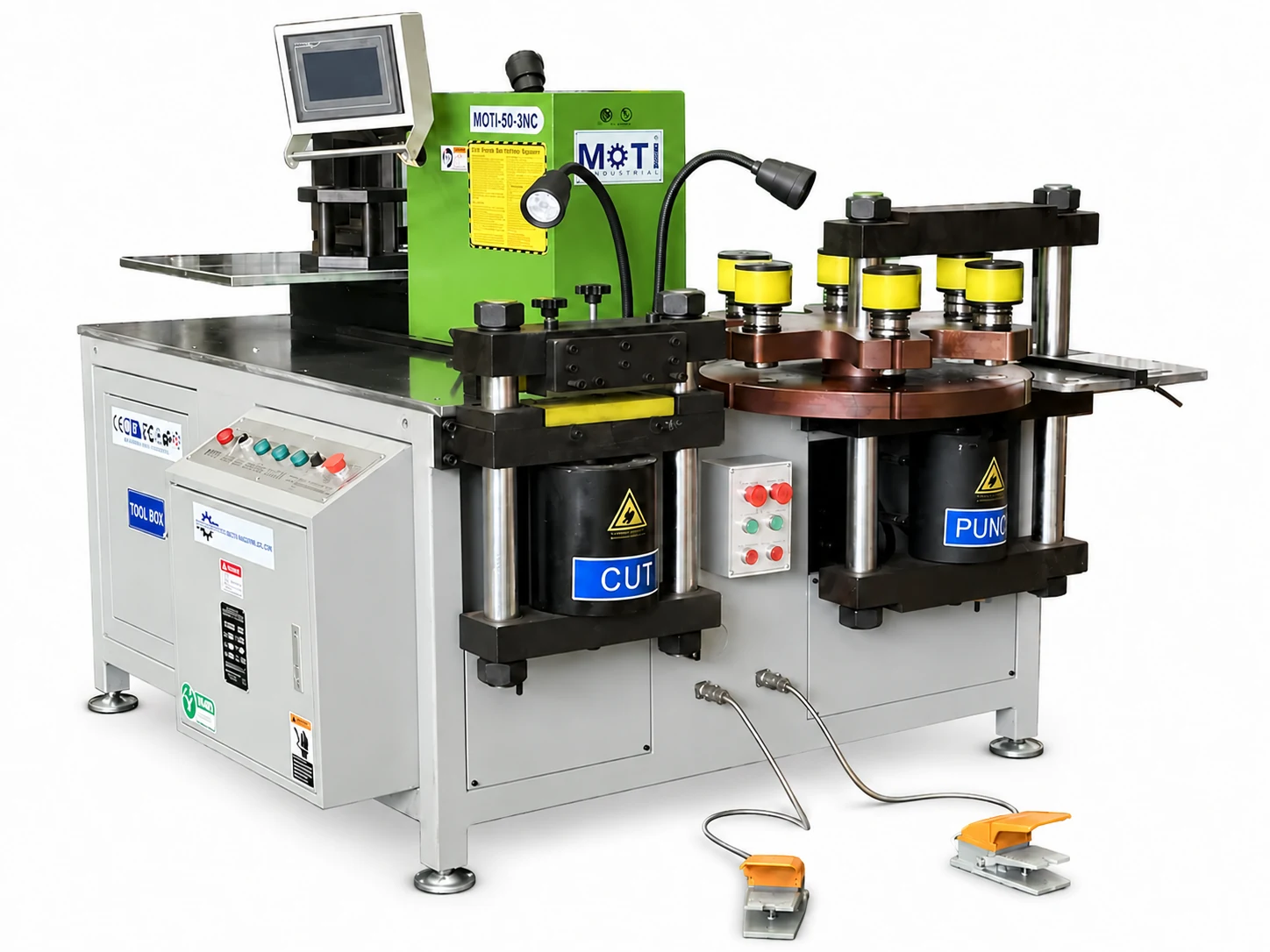
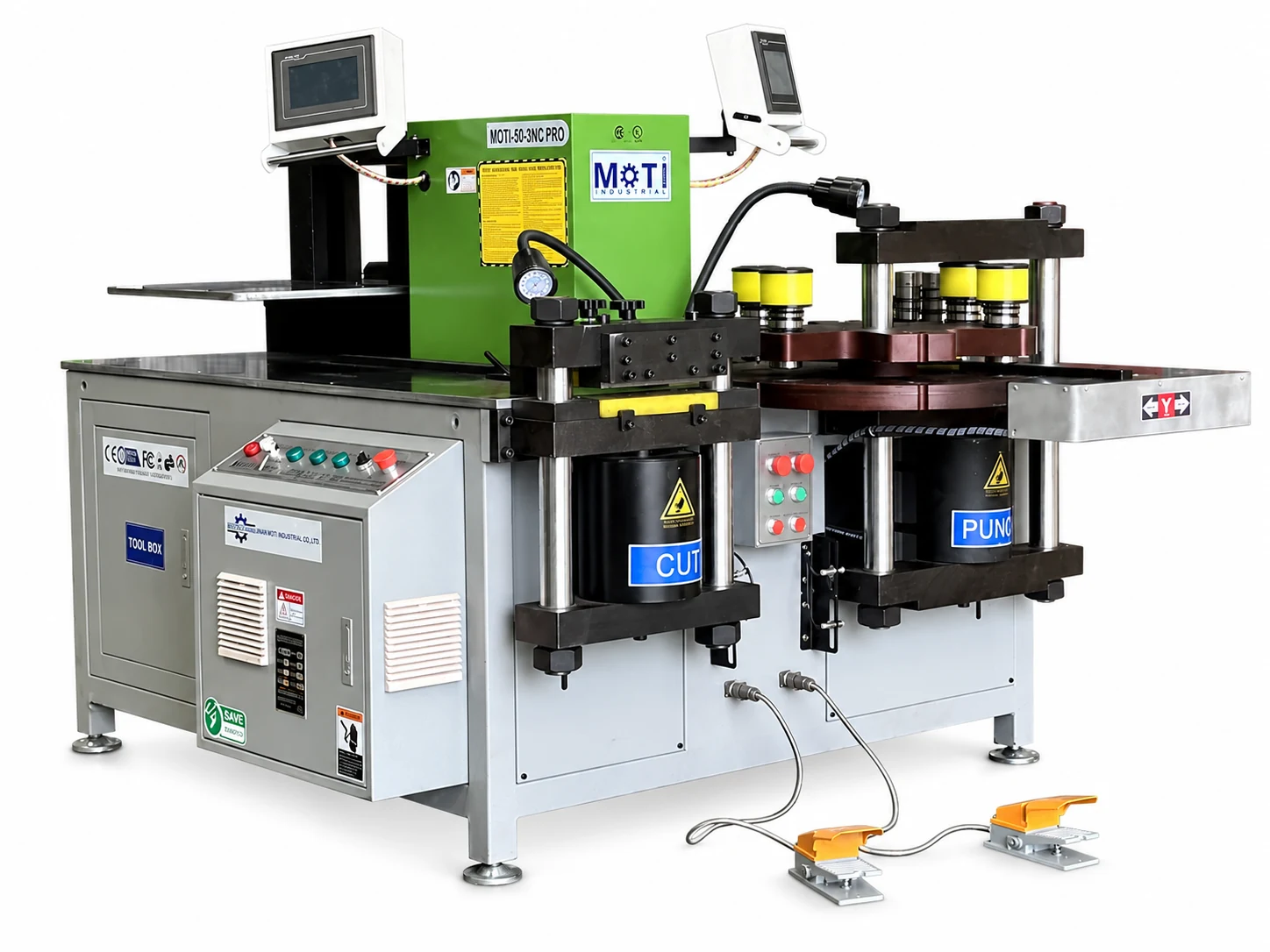
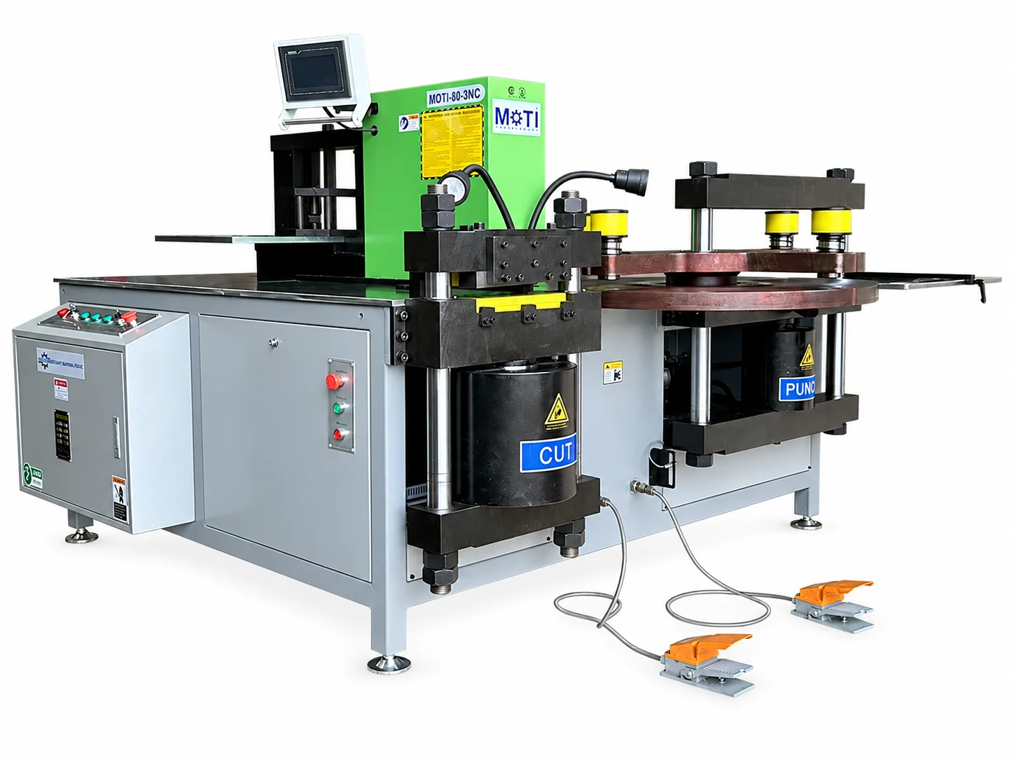
| Standard three-in-one machine | Mixed work frequently needs punching, cutting and bending in one compact cell. | Complete batch trial, changeover record and operator allocation. |
| Two punching stations plus cutting | Punching queues are persistent, bending demand is limited or already covered, and tool families can be divided. | Station-by-station time, tool map, material route and good-parts count. |
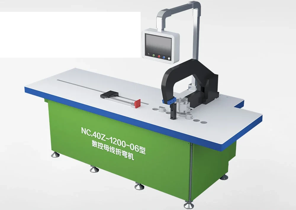
| Automatic punching and shearing | Long bars, repeat hole sequences or larger batches make manual locating and handling a major part of the cycle. | Same-part program trial, loading assumptions, inspection results and downstream flow. |
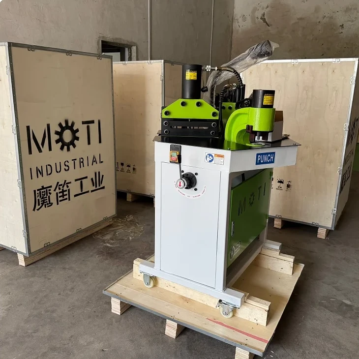
The MOTI busbar machine range provides the starting categories. For a custom station mix, review the custom tooling and workflow service together with the machine layout. Tool quantity alone does not prove that the selected hole sizes fit the turret openings or the proposed process.
Run an A-B comparison and watch where the queue moves
Test a representative batch on the current route, then test the proposed task split. Record good parts per shift, operator time, tool-change time, waiting, inspection and rework. Keep the acceptance drawing unchanged. If punching improves but cutting, inspection or handling begins to queue, the bottleneck has moved and the next investment decision should use that new evidence.
The earlier guide to returning to a previous busbar job is relevant when each station will hold a different tool set or product family. Stored coordinates, physical tools and workpiece references must all return together; saving only a program name does not restore the setup.
Information to send for a configuration review
Prepare three to five representative drawings, a hole-size and slot list, batch quantities, maximum bar section and length, current shift data, available operators and a simple floor plan. State which cutting and bending equipment will remain in the route. If the existing problem is frequent tool change, include the current change sequence and the time required to restore a previous job.
Also define the acceptance method: hole position, hole size, burr condition, part identification and the number of consecutive good parts required. The UAE double-punch project page shows the published reference configuration, while your order still needs its own tool list, support layout and trial.
Send MOTI your representative drawings, hole schedule, batch mix and current punching-time record. MOTI can then compare a standard three-in-one machine, a two-punch custom layout and an automatic punching-shearing route against the same production evidence.
Sources: MOTI's published UAE two-punching, one-cutting project and MOTI-50-3NC product materials, checked 13 September 2026. The project configuration is manufacturer-published information. Workflow recommendations are a purchasing-test method and do not claim a guaranteed throughput increase.