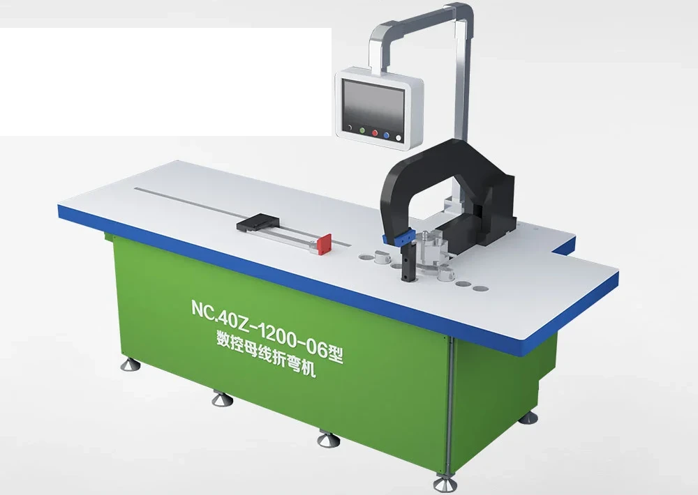
A busbar duct connector can have a correct bend at each end and still fail to fit the assembly. The two ends belong to one finished part, so their spacing, direction, offset and orientation must be reviewed together.
That changes how a bending process should be specified and tested. Start with the complete connector drawing, establish one datum system, and inspect the relationship between both ends after forming. A cropped drawing of one end cannot define the whole job.
Begin with the complete finished connector
Provide the full flat and formed views, drawing number and revision. Identify the material and condition, thickness, width, finished overall length, internal radii, bend angles, offsets and any holes that act as assembly references. Mark end A and end B so that mirrored or reversed parts cannot be confused.
Show which face is up at each end and which direction each bend moves from the original flat bar. If the connector mates with two housings, joint packs or busbar runs, include the assembly references that control fit. The busbar tooling and sample guide explains why the finished geometry and mating references should define the tool discussion.
Use one datum system for both ends
Choose the drawing references that will be used during forming and inspection. An end dimension measured only from a nearby cut edge may look correct while the total relationship between end A and end B is wrong. Record the overall length, the location of each formed feature from the agreed datum, and the dimensions that determine assembly fit.
Keep the same datum language in the drawing, tool proposal, setup record and inspection sheet. If one end is mirrored, state that explicitly rather than relying on a photograph. Also show how the part will be oriented when it enters the machine so the operator can distinguish the two ends.
Review the bend sequence and formed-part envelope
A tool that produces one bend may not have enough access after another flange has formed. Review the full order of operations, the shape after each stroke, where the bar is supported and whether the tool or machine structure can clear the already formed end.
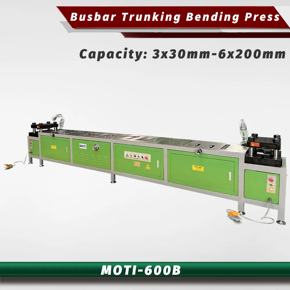
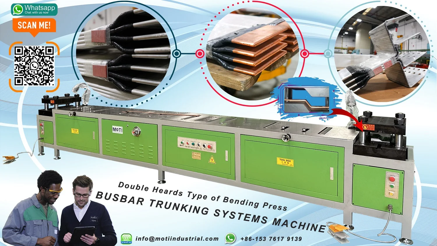
For a double-head process, confirm which shapes are made in one setup and which adjustments remain manual. The MOTI-600B product information describes two hydraulic bending heads and manual control. That does not imply automatic loading, unloading or inspection. Ask the demonstration to show the placement, end positioning, forming, removal and measurement of the same complete part.
The material-handling workflow guide can be used to check support space for the flat blank and the larger envelope of the formed connector.
Match the machine route to the actual application
The MOTI-600B is intended for paired end forms on busbar duct and busbar trunking connection bars. Its published working range is 3 × 30 to 6 × 200 mm, with a 60 Ton force listing, 4 kW motor, manual control and two hydraulic working ends. Those figures are an initial selection reference, not proof that every shape inside the thickness and width range fits the same dies.
This is a bending machine. Plan upstream cutting and punching separately when the connector also needs holes or a controlled blank length. A changing mix of unrelated U, Z or single-end shapes may require a different bending route. Compare the machine around representative drawings rather than treating a dedicated two-end process as a general three-in-one workstation.
Control the drawing and tool as one revision
Assign an identifier to the matched tools and record which drawing revision they support. If the connector length, offset, radius or mating reference changes, assess the effect on the tool and setup before running the next sample. Do not approve a tool against one revision and later measure the part against another.
The drawing revision control guide shows how to keep the drawing, tool, setup, sample and result aligned. For a dedicated two-end connector, that link is especially important because a small change at one end can alter the relationship to the other.
Trial the whole part and inspect the relationship
Use the intended material, thickness and width for the trial. Record the machine and tool identifiers, drawing revision, operator, setup conditions and sample number. Inspect each end, then inspect the dimensions that connect the two ends: overall length, relative positions, offset, orientation and any drawing-defined assembly references.
A photograph can document appearance and orientation, but it does not replace measured results. Where assembly fit controls acceptance, test the connector with the agreed mating reference or a defined inspection fixture. Keep failed, corrected and accepted results in the same history instead of retaining only the final sample.
The sample acceptance record provides a practical structure for measurements, result status and approval scope. Acceptance applies to the tested material, geometry, tool and revision; it does not automatically cover untested parts.
Measure the complete production cycle
Start timing when the identified blank is collected and end when the formed connector has been inspected and placed in its next location. Separate loading, positioning, adjustment, forming, removal, inspection and changeover. If the process reduces turning or repeated positioning, the trial should show that difference with the same part and staffing.
Do not convert one forming stroke into a finished-parts-per-hour promise. The complete production-trial method helps compare preparation, stable running, inspection and recovery without hiding manual work outside the machine cycle.
Put the agreed process into the quotation
List the exact machine version, matched forming tools, supported size and geometry, adjustment method, sample trial, inspection points and any upstream or downstream work that remains outside the machine. State which drawings and revisions define the supplied tools. Separate included items, options and buyer-supplied fixtures.
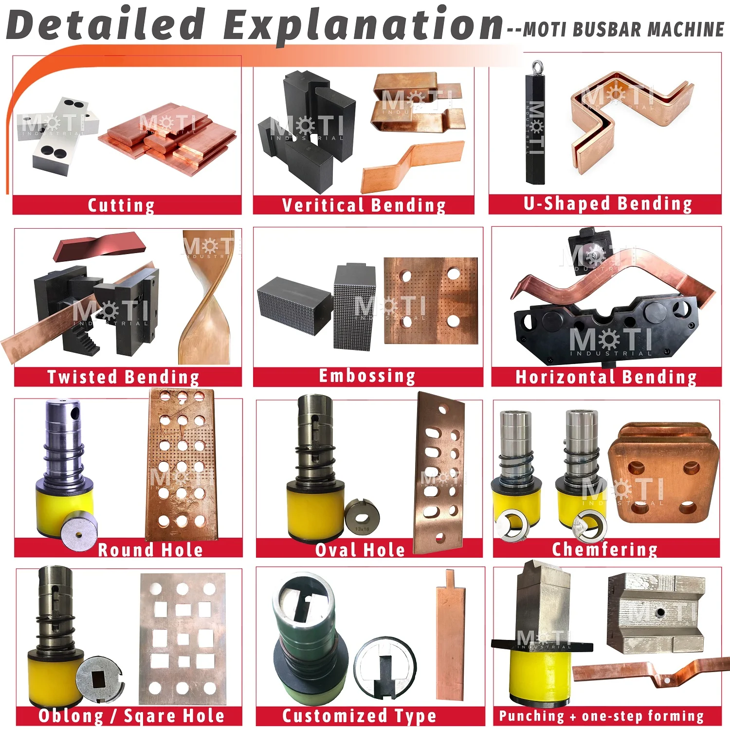
Send MOTI the complete two-ended connector drawing, material, thickness and width, total length, end geometry, batch information and assembly references. We can review whether the dedicated double-head route matches the part and define what must be demonstrated in the trial.
Sources: MOTI-600B product information and MOTI drawing, tooling and sample-trial records, checked 22 September 2026. Published figures are manufacturer values for initial selection; the final drawing, tooling proposal, quotation and sample acceptance define the supplied application.