
A busbar bending angle is the result of a complete setup, not a number entered on a screen. The machine movement, tool geometry, material condition, thickness, bend direction, support and measurement method all affect the finished part. If one of them changes, reusing the previous compensation without a check can create a repeatable wrong angle.
Calibration should therefore connect one machine and tool setup to one defined material and acceptance method. The aim is to make the result traceable and repeatable, while keeping machine-specific adjustment work inside the manufacturer’s instructions and qualified personnel.
Define the finished angle before adjusting the machine
Start with the governing drawing and its revision. Mark the required angle, bend direction, inside radius, datum faces and any leg or end dimensions that affect assembly. State the tolerance only when it comes from the approved drawing or purchase agreement; do not invent one general tolerance for every busbar.
Agree how the angle will be measured. Identify the instrument, contact faces, sample orientation, measurement location and whether the reading is taken after the part is removed and allowed to relax. A screen value, a scale on the table and the finished-part angle are different observations. The accepted result belongs to the finished part.
The drawing revision control method helps keep the drawing, program, tool and sample linked before any compensation value is approved.
Establish the machine and tool baseline
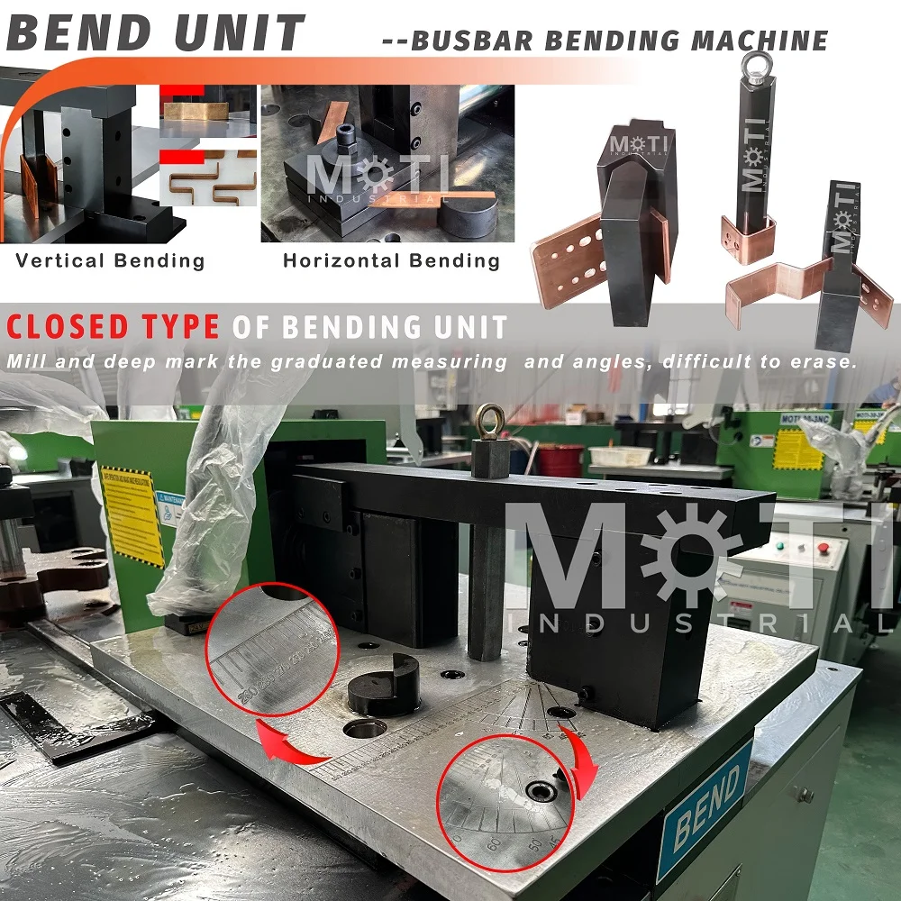
Record the machine model and serial number, controller or software version where relevant, bending station and installed tool identifiers. Check that the selected upper and lower tools belong together and match the intended bend direction, thickness and radius. A tool that fits physically is not automatically the correct or approved pair.
Any zero, origin, stroke or tool-height check must follow the instructions for that exact machine and configuration. Do not copy a calibration sequence from another model or bypass a guard to reproduce a video. If the baseline cannot be confirmed, stop and send the model, serial number, tool details and observed condition to technical support.
Treat springback as a material and process condition
After the forming load is removed, the part can recover elastically toward its original shape. The amount is not a universal constant. It can vary with material type and condition, thickness, bend direction, radius, tool contact and the actual process. A compensation established on one material batch should not silently become the setting for every future order.
Use a representative sample from the intended material and thickness. Record the material identification, width, thickness, tool set, target angle, machine input or position, measured result and approved correction. Keep the uncorrected observation rather than overwriting it; that first result explains why the compensation exists.
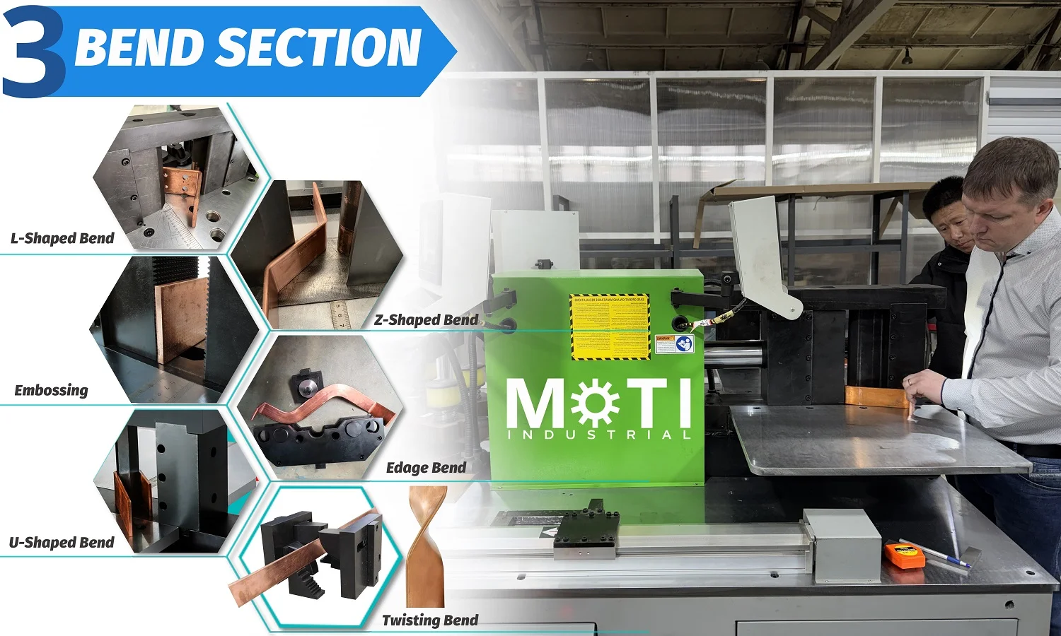
For a new material, thickness, tool or bend direction, run a controlled first-piece check again. The flat-versus-edge bending guide explains why direction-specific capacity and tooling cannot be treated as interchangeable.
Apply compensation as a controlled setup value
Once the baseline and measurement are confirmed, qualified personnel can apply the machine-specific correction described in the applicable instructions. Record who made the change, the previous value, the new value, the reason and the sample that verifies it. Avoid changing several parameters together because the result will not show which change mattered.
Do not chase every individual part by continually editing compensation. If a stable setup begins to drift, preserve the last accepted state and investigate the material, tool condition, positioning, support, program revision and measurement method. The technical support evidence guide lists the information needed when the expected result cannot be reproduced safely.
Keep accuracy and repeatability as different questions
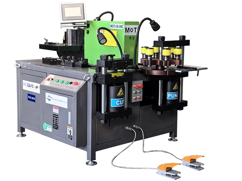
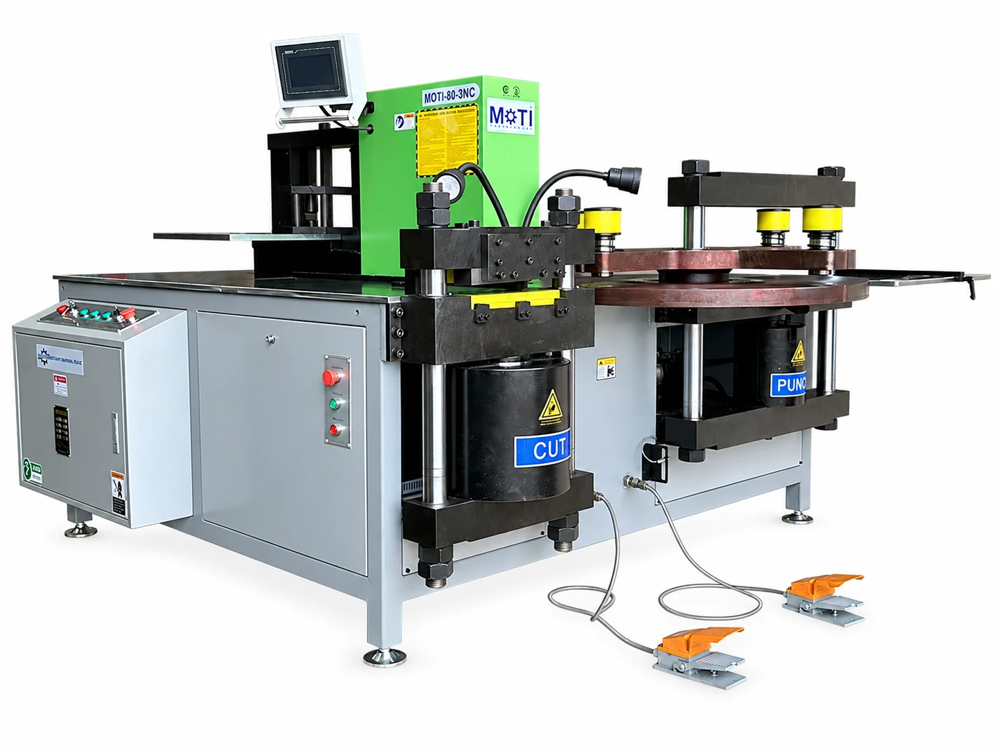
MOTI’s published standard-series records list bending accuracy and repeat bending accuracy as separate values: ±1° and ±0.3° respectively for the referenced 30-3NC, 50-3NC and 80-3NC pages. Those two figures should not be combined or interpreted as a guarantee for every part, tool and material.
Accuracy asks how close the measured part is to the approved target. Repeatability asks how closely several parts agree under the same controlled setup. A group of parts can agree with one another and still all be offset from the target. Conversely, adjusting each part toward the target can hide poor repeatability.
Check the first part against the target, then measure a defined repeat set without changing the setup. The quantity, dimensions and acceptance rules should come from the purchase or trial plan. Use the sample acceptance record to preserve each measured result instead of reporting only an average or a selected good part.
Record changes that invalidate the approved setup
A useful calibration record states when it may be reused and what requires rechecking. Typical triggers include a different material specification or batch, thickness, bend orientation, tool set, radius, machine, controller or program revision, maintenance affecting the bending station, or a changed measurement method.
Label the approved setup with the part and drawing revision rather than a vague filename such as “90 degree final.” Store it with the tool identifiers and sample record. If a superseded value must be retained for traceability, keep it unavailable for accidental production selection.
The fixed tooling and sample guide provides the broader drawing and tool information needed before a bending trial.
Use a simple calibration and verification table
One row should identify the date, machine and serial number, controller version, tool pair, drawing revision, material and batch, thickness and width, bend direction, target angle, input or position, measured angle, correction, repeat results, instrument and reviewer. Attach photographs only as context; they do not replace the measured record.
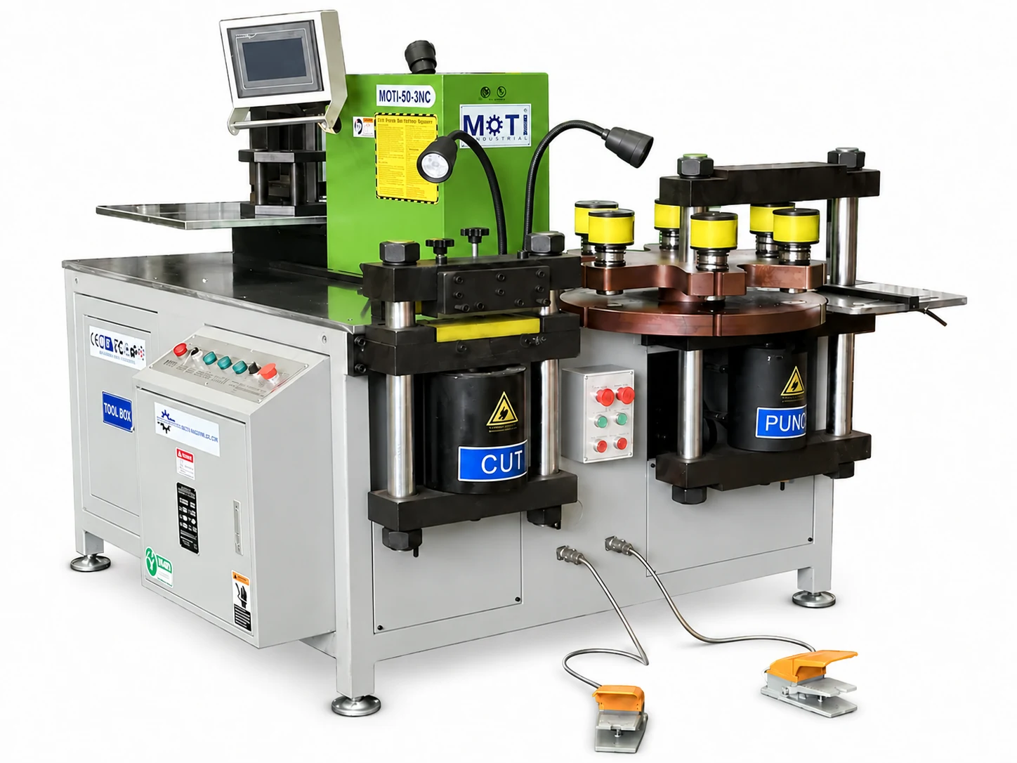
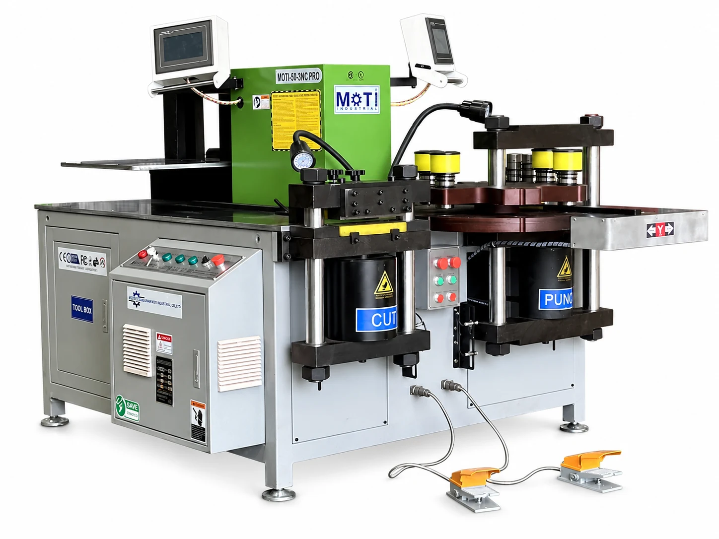
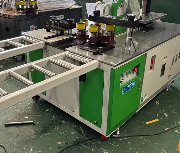
For heavier or wider work, also record support and handling because uncontrolled weight or contact can change how the part sits at the station and how it is measured. The MOTI-30-3NC, MOTI-50-3NC and MOTI-80-3NC pages show different working ranges; the actual quoted configuration and sample trial define the applicable setup.
Ask the supplier to demonstrate the complete loop
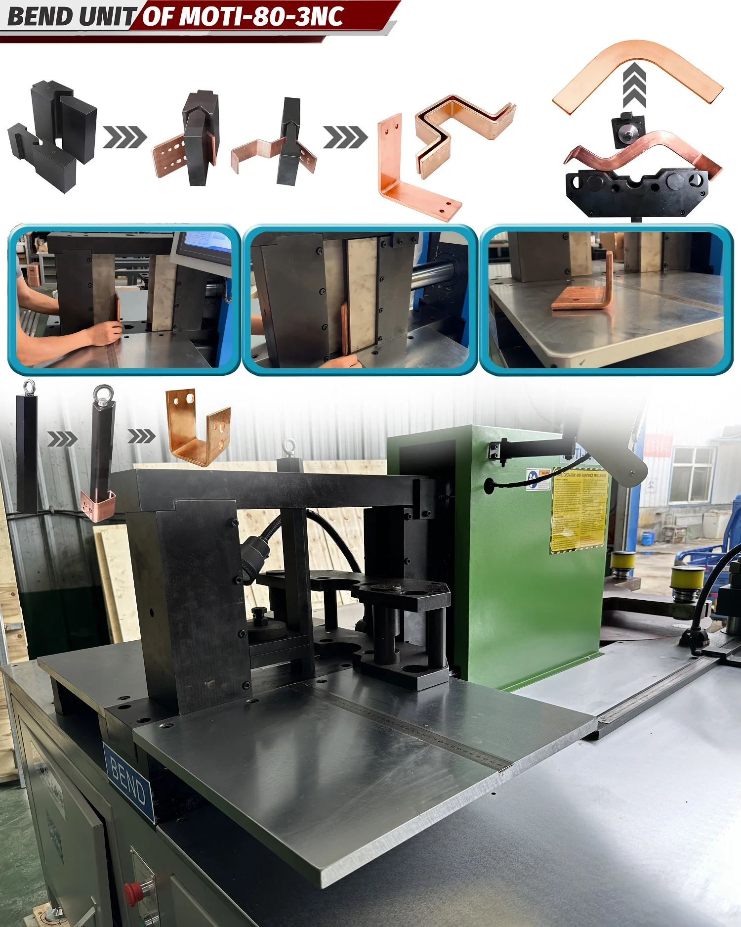
During a machine evaluation, provide a representative drawing and material. Ask the supplier to identify the machine and tool baseline, make the first part, measure it by the agreed method, record any approved correction and then produce the repeat set without hidden changes. Include a normal material or job change so the operator can show when the earlier value may be reused.
Send MOTI the drawing revision, material and condition, thickness and width, bend direction and radius, required angle and tolerance, planned quantity and current machine or tool information. We can define the relevant machine, tooling and sample-trial scope before discussing a calibration record.
Sources: MOTI-30-3NC product record, MOTI-50-3NC product record, MOTI-80-3NC product record, MOTI bending calibration FAQ, and internal sample, support and revision-control guidance. Source links checked 16 October 2026. Adjustment procedures must follow the exact machine instructions and qualified personnel; no universal compensation value is claimed.