
A message such as “the bend is inaccurate” or “the machine has an alarm” identifies a symptom, but it rarely gives technical support enough evidence to separate a material, tooling, program, setup or machine issue. The fastest first step is a controlled support record that ties the symptom to one machine, one configuration and one repeatable process.
Collect the information below before changing parameters or replacing parts. It gives the support team a reproducible starting point and helps avoid advice based on the wrong model or operating condition.
Identify the exact machine and configuration
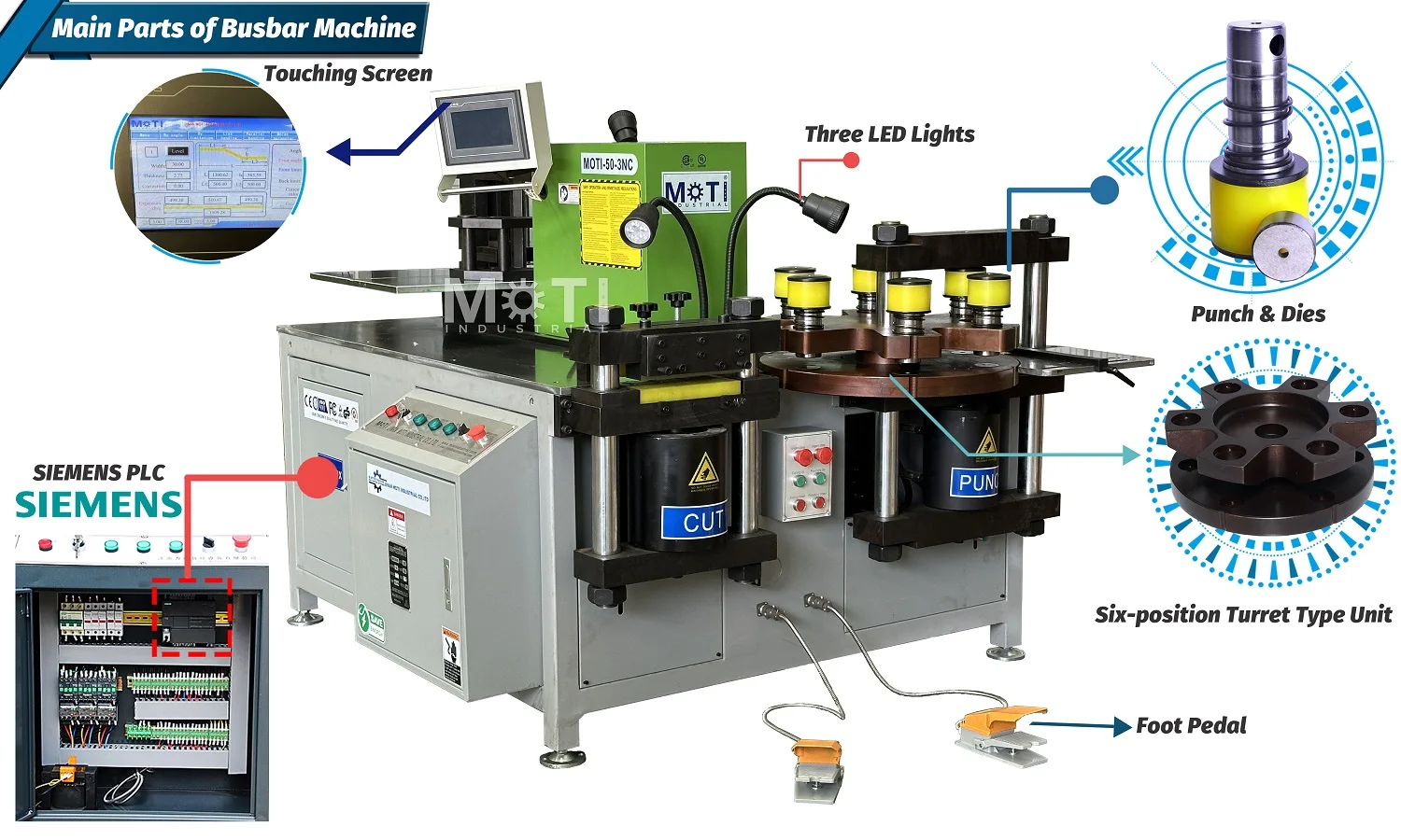
Start with the full model, machine serial number and purchase or configuration version. Add the controller or software version where it is visible, plus any option or modification related to the affected station. A family name alone is not enough because controls, positioning systems, tools and interfaces can differ between versions.
Photograph the machine nameplate and the controller version screen rather than typing them from memory. If a serial plate, program or drawing contains customer-sensitive information, crop unrelated order and personal data before sending it.
Copy the exact alarm and describe when it appears
Record the complete alarm text or code exactly as displayed. State whether it appears at power-up, homing, program loading, tool movement, positioning, punching, cutting, bending or return. Include what the machine was doing immediately before the message and whether a restart changes the symptom.
A clear sequence is more useful than a diagnosis guessed on site. For example: “The X axis homes normally. The alarm appears after the third positioning move in program A12, before punching.” That sequence lets support compare the event with the controller version and program step.
If there is oil leakage, unexpected movement, damaged protection or any unsafe condition, stop the machine and keep people clear. Do not bypass a guard or interlock to produce a video. Inspection and corrective work should follow the instructions for that machine and be performed by qualified personnel.
Reconstruct the last good cycle and the failed cycle
Write down the last time the operation completed normally and the first time it did not. List the steps in order: load material, select program, establish the datum, select or install the tool, position the part, run the operation and inspect the result. Mark the exact step where the result changes.
Also state whether the problem occurs on every cycle, intermittently, on one program, with one operator, on one material batch or only after the machine has been running for a period. Do not change several settings at once while collecting evidence; that makes the cause harder to isolate.
Connect the symptom to the material, tool and program
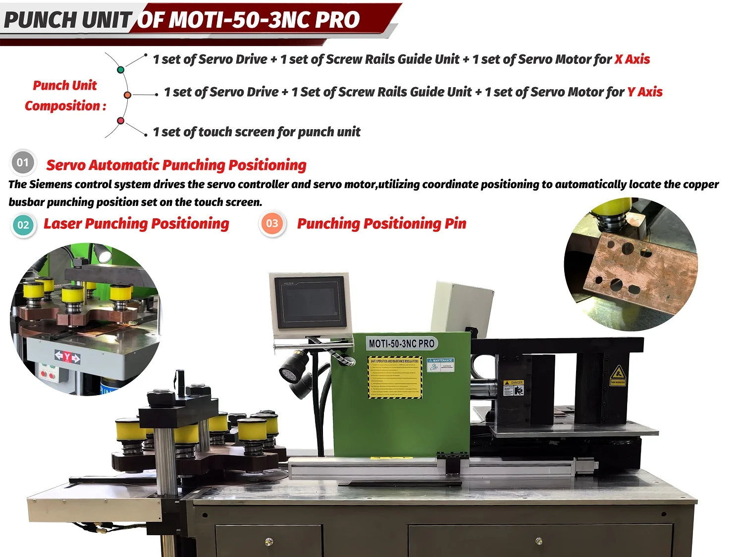
For the affected part, provide the drawing revision, material, width and thickness. Identify the upper and lower punch, bending tool or blade arrangement, including any tool number visible in the supplied records. State the datum or gauge used, the program name and version, and the target and measured result.
For a bending deviation, report the target angle, measured angle, thickness, material change, bending tool and the relevant calibration record. For a hole or cut problem, show the matched upper and lower tool or blade condition, material and positioning method. For inconsistent positioning, report the datum, gauge or axis, program version and one identified sample.
The drawing revision control guide helps keep the support evidence tied to the correct part definition. Use the sample acceptance record to label the part and compare required and measured results.
List every recent change
Many useful clues sit outside the alarm screen. Note any recent change in material supplier or batch, thickness, tool, program, datum, calibration, maintenance, replacement part, hydraulic or electrical work, machine relocation, ambient conditions or power supply. Include the date and whether the symptom began before or after the change.
If the machine was recently installed or moved, compare the record with the site power preparation checklist. Voltage, phase, frequency, grounding and local protection should be checked against the exact machine documents by qualified personnel.
Take photos and video that preserve the sequence
Use one overview photo to show the station and material position, then detail photos of the controller screen, tool, datum, finished feature and any visible damage or leakage. Keep the camera steady and include a ruler, angle gauge or identified measurement when it is part of the symptom.
A useful video begins before the affected step and continues until the symptom appears. Show the screen and machine area from a safe position, with sound when it helps document an abnormal noise. Do not stage a repeat if doing so could damage the machine, tool or workpiece.
Provide part-specific details for a spare request
A component name or photo alone may not establish compatibility. Send the machine serial number, part identifier, interface dimensions, current-part photo, material or electrical rating where relevant, replacement version, required quantity and reason for replacement. Punches and dies should be checked as a matched set.
Do not assume that a visually similar electrical, hydraulic or tooling component from another model or brand is interchangeable. The final match should follow the original configuration and be confirmed for the specific serial number.
Use one structured support message
Put the model and serial number in the subject line. In the message, list the controller version, exact alarm, process step, material and size, tool, program or datum, target and measured result, recent changes, frequency of occurrence and the attached photo or video names. The wider delivery, installation and support guide explains which machine records should remain available after commissioning.
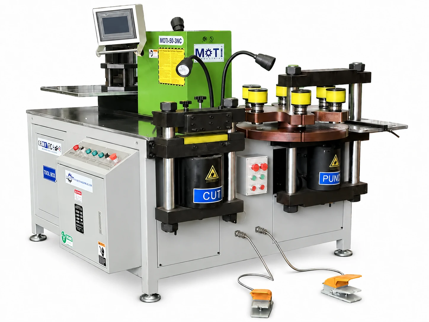
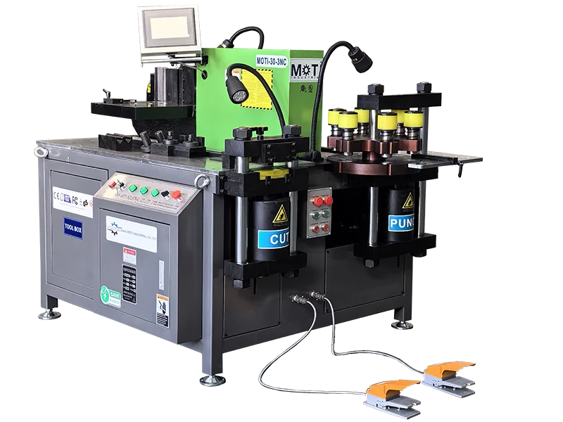
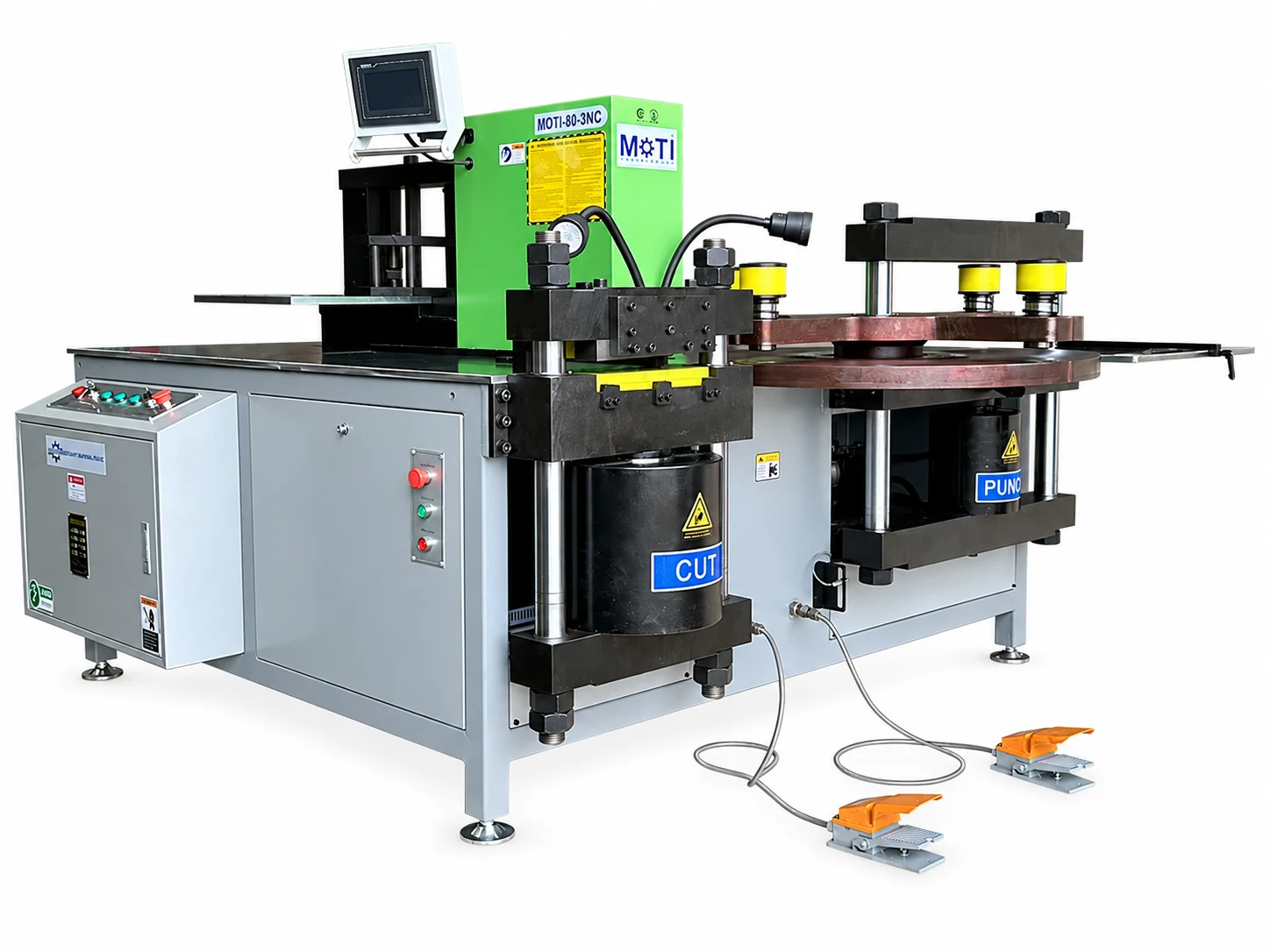
The MOTI-50-3NC product record is an example of a model-specific reference. Support should still use the actual nameplate, configuration and documents supplied with your machine.

Send MOTI the machine model, serial number, exact alarm or symptom, affected process, material, tool, measurements and safe photos or video. A structured record gives technical support a clear basis for the first assessment.
Sources: MOTI support, installation, procurement and product records, checked 20 September 2026. This article is an information-collection guide; it does not replace the machine manual, a qualified safety assessment or model-specific repair instructions.