
By MOTI Industrial · 13 September 2026
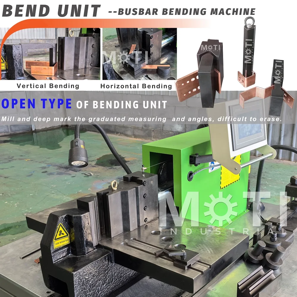
A busbar machine may publish one large bending range and a smaller range for another direction. That is not a contradiction. Turning a rectangular bar changes the section presented to the tool, the space needed around the bend and the way the workpiece must be supported. A capacity stated for one orientation should not be carried across to another.
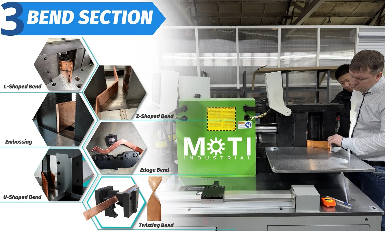
The first practical step is to mark the bend direction on the finished-part drawing. Terms such as flat bending, edge bending, horizontal bend and vertical bend are not always used consistently between suppliers. A simple cross-section sketch is safer than relying on the name alone.
Start with the bar cross-section and the bend plane
Record the copper or aluminium grade and condition, then write the actual thickness and width as separate dimensions. On the drawing, show which face is inside the bend and identify the required inside radius. This tells the supplier how the rectangular section is oriented when it enters the tool.
The same 12 × 100 mm bar can present a different section to the bending tool when the bend plane changes. The tool, opening, support and available clearance may therefore differ. The busbar drawing review checklist explains how to keep datum and orientation information clear; use the same discipline for every bend view.
Read each published range with its own label
MOTI’s standard three-in-one model tables separate the main bending range from another direction labelled “Horizontal Bend.” The values below reproduce those published labels rather than renaming the directions.
| Model | Main bending range | Other direction labelled “Horizontal Bend” |
|---|---|---|
| MOTI-30-3NC | 12 × 160 mm | 100 × 10 mm at 90° (width × thickness in the source table) |
| MOTI-50-3NC | 16 × 250 mm | 120 × 12 mm at 90° (width × thickness in the source table) |
| MOTI-80-3NC | 20 × 300 mm | 120 × 12 mm at 90° (width × thickness in the source table) |
These are manufacturer-published selection values, not permission to combine the largest thickness from one row with the largest width from another. If your drawing calls for several bend directions, check every direction separately. The MOTI busbar machine range gives the wider equipment context, while the individual model page remains the source for its operation-specific limits.
Check radius, flange and nearby features
Thickness and width are only the first screen. The required inside radius affects the tool choice, and a short flange may leave too little room for the intended support or locating method. Holes, slots or a previous bend near the new bend line can also change how the part sits at the workstation.
Send the formed drawing, not only the flat blank. Include the bend sequence when one bend could interfere with access for the next. If the supplier proposes a different sequence or tool, record that proposal against the same finished geometry so it can be reviewed by the designer and workshop team.
Do not treat a larger model as an automatic answer
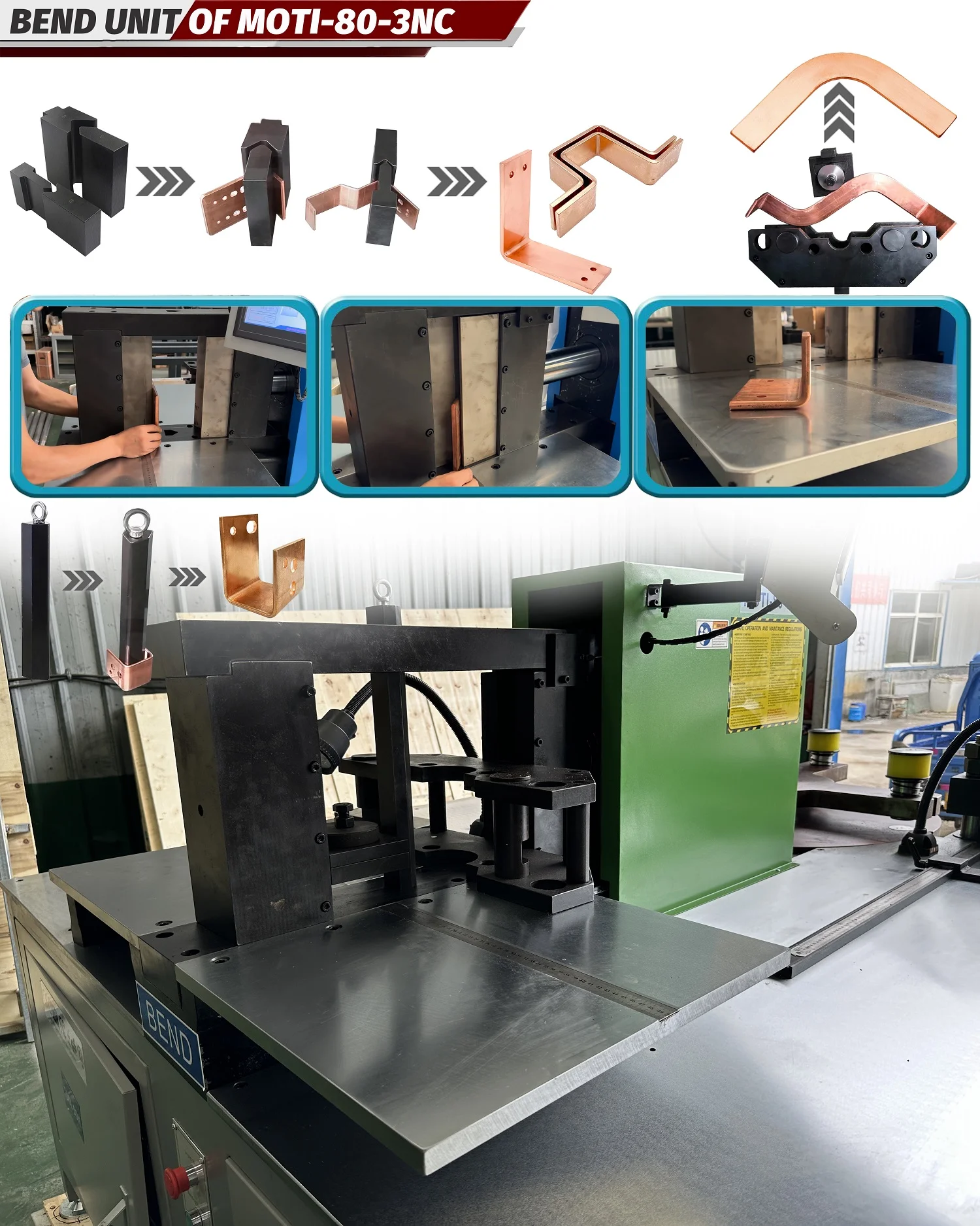
A higher-force model can increase the published main range, but the second-direction figure may not increase by the same amount. The MOTI-80-3NC page, for example, publishes 20 × 300 mm for the main direction while retaining 120 × 12 mm for the other labelled direction. That is why the largest headline number cannot stand in for a complete bend review.
Use the MOTI-80-3NC model page when heavy parts point toward that class, then confirm the exact drawing with the proposed tool set. If the part is within a smaller class, the MOTI-50-3NC model page provides the corresponding published limits. Model selection should follow the most demanding required operation, not the largest number on a comparison card.
Use a drawing-based bending trial
For an important or borderline part, ask the supplier to identify the exact machine configuration and tool before the demonstration. Record the material, actual cross-section, bend direction, inside radius, target angle, flange dimensions and the inspection method. The tooling and sample preparation guide can be used to organize the tool and sample information.
Check the completed part against the agreed drawing and acceptance method. If the demonstration uses a different material condition, radius or orientation, treat it as a different test. A successful flat bend does not establish edge-bending capacity, and a single edge-bending sample does not prove every geometry inside a nominal rectangle.
When requesting a quotation, attach the finished drawing and highlight every bend direction that the machine must make. Send MOTI your maximum cross-section, bend views and required radii so the machine and tooling can be reviewed against the actual part.
Sources: MOTI-30-3NC, MOTI-50-3NC and MOTI-80-3NC manufacturer product tables, checked 12 September 2026. Direction names are reproduced as published because terminology can vary; final selection should use a cross-section drawing and a configuration-specific demonstration.