
By MOTI Industrial · 15 September 2026
A custom busbar tool should be reviewed against the connection it must assemble, not only against the flat copper blank. A hole can be the correct diameter and a bend can reach the requested angle while the finished part still fails to align with a breaker terminal, support or neighbouring conductor.
The assembly drawing provides the missing context. It shows which faces and hole centres control fit, how bends relate to those references and where the part must clear surrounding hardware. Start there before discussing a special punch, bending die or combined forming tool.
Identify the mating parts and functional datums
Mark the surfaces, hole centres or edges that locate the busbar in the final assembly. If a breaker terminal drawing controls the connection, include it or provide a simplified interface drawing with the critical dimensions. State whether dimensions are taken from the flat blank, the inside of a bend, the centreline or a finished mounting face.
The earlier busbar hole-pattern drawing checklist explains datums, mirrored orientation and slot direction. A custom-tool review goes one step further: it must connect those manufacturing dimensions to the part that the busbar will actually meet.
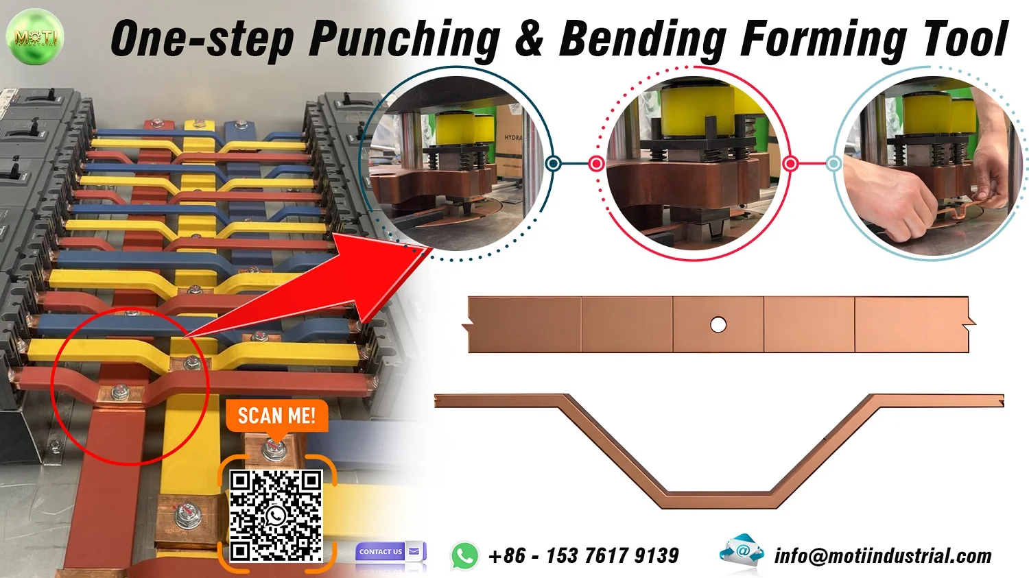
Describe the finished geometry, not just the hole
For each connection, provide material, thickness, width, hole shape and size, slot direction, edge distance, centre spacing and the required finished bend geometry. Add the inside radius, bend direction, flange lengths and the distance from the bend to the locating hole. Show both the flat view and the formed view when either alone could be misunderstood.
A nominal hole size does not define punch-to-die clearance, turret fit or waste discharge. Likewise, a nominal 90-degree bend does not define the tool opening, inside radius or space needed for a short flange. The flat and edge bending capacity guide explains why the bar orientation and bend plane must be shown rather than inferred from one direction name.
Separate critical assembly dimensions from reference dimensions
Mark the dimensions that decide whether the connection can be installed and inspected. Examples include terminal-hole alignment, distance between two mounting faces, finished offset, clearance to insulation and the relative position of holes after forming. Reference dimensions can help the tool designer understand the part, but they should not compete with the actual acceptance dimensions.
List tolerances only where the drawing or assembly requires them. Do not apply one general tolerance to every feature or ask the tooling supplier to invent an acceptance limit. Material condition, burr direction and surface requirements should also be stated when they affect contact, coating or assembly.
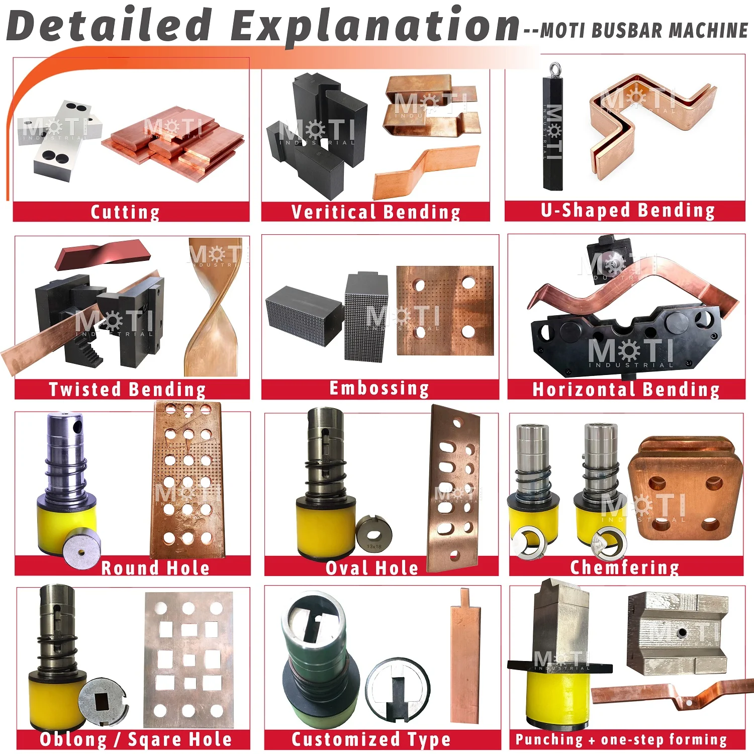
Check the machine and tool interface together
Provide the machine brand, model and serial information for an existing machine, plus photographs and measured dimensions of the mounting interface. A punch with the right cutting profile may still be incompatible with the holder, stripper, turret opening or available working height. For a new machine order, identify the proposed model and the exact workstation where the tool will run.
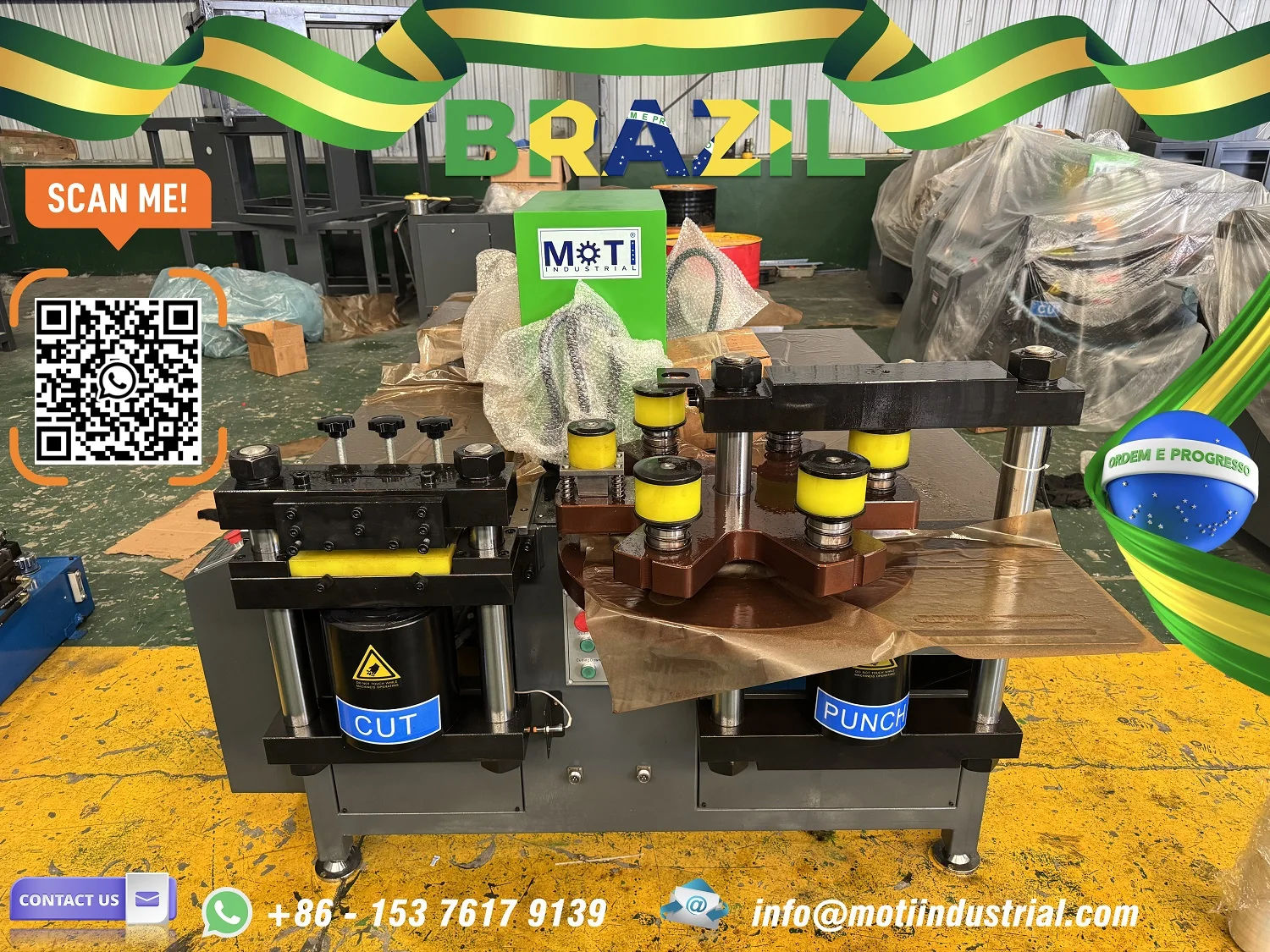
The MOTI-50-3NC model page shows the equipment context for the HEMACK project. Its published model table should be used for initial machine screening, while the connection drawing and tool drawing control the project-specific review. A case article mentioning a different width from the standard model table should not be used to silently expand the standard range.
Decide whether one-step forming is the right process
A combined punch-and-bend tool can reduce separate handling for a suitable connection, but the decision should come from the complete part. Check whether the blank can be located consistently, whether the formed section can leave the tool without interference and whether the critical hole-to-bend relationship can be measured after forming.
Compare the proposed combined operation with separate punching and bending on the same drawing. Record setup, operator steps, first-piece inspection, consecutive good parts and changeover to another connection. If the part family varies widely, separate tools may provide more flexibility even when one combined tool works well for a single part.
The custom busbar tooling service and tooling and sample preparation guide provide the wider review path. Use them to build the tool list and trial plan rather than treating a project image as a complete specification.
Approve a tool drawing before manufacturing
The approval package should identify the customer drawing number and revision, workpiece material and section, finished part orientation, machine interface, upper and lower tool pairing, locating method and the dimensions to inspect. Assign a tool number that can be carried into the sample record and future reorders.
When the drawing changes, record whether the tool remains usable, needs modification or must be replaced. Keep the accepted tool drawing with the matching workpiece revision. This prevents a later production team from assuming that a physically fitting tool is approved for a revised connection.
Use the sample to verify the assembly requirement
Run a documented first piece and a short repeat sequence using the agreed material. Measure the critical finished dimensions, inspect the hole and formed surfaces, and test the part against the mating interface or a controlled fixture. Record the machine, tool number, drawing revision, material batch, operator and results.
The HEMACK Brazil project page is a useful reference for discussing dedicated connection tooling. A new project still requires its own drawing, tool interface and acceptance evidence.
Send MOTI the assembly drawing, mating interface, material section and machine details. MOTI can review whether a standard punch, dedicated forming die or combined punch-and-bend tool fits the actual connection.
Sources: MOTI’s published HEMACK Brazil project, MOTI-50-3NC product information and MOTI tooling records, checked 14 September 2026. HEMACK project details are manufacturer-published information; the drawing and acceptance steps are a purchasing-review method, not a guarantee for untested parts.